hi all , so quite here where is all the fun?? where are all the people??
This thread is 10+ years old....
There is a vast amount of information here, it's all searchable, and many good folk are still subscribed, some will even respond, if you ask adroit questions...
^ I too can vouch for the Eminence Magnum 12HO, it isn't cheap but it is well made and works well for TH's (25Hz-35Hz tuned). It may not have the greatest Xmax but I know that it's pretty damn bulletproof.
Perhaps the Eminence 3015LF would give more output overall, so this might be another one to consider?
I Concur, mines still working

10 years
https://www.diyaudio.com/forums/att...ped-horn-project-naudio_eminence_4section-jpg

I wonder how this has all evolved, if there has been any significant gain over older designs from back in the day.
For anyone building.
some feedback.. (of the good kind?) and thanks!
Im happy with what I built. so for anyone who would build what I did; Im sure they would be content. for home use. good resonance, well defined tones, good fundemental tuning, good roll off at higher bass frequencys. good volume.
still firing
Last edited:
Mine are doing great too.
Eminence Kappa Pro LF2's still producing the lows.
I had to cut them in half to get them up a tight staircase to a new music loft 3 years ago..
Height and bannister/rail was the problem. Rebuilt them up there - Good as new. Birch plywood is easy to work.
Eminence Kappa Pro LF2's still producing the lows.
I had to cut them in half to get them up a tight staircase to a new music loft 3 years ago..
Height and bannister/rail was the problem. Rebuilt them up there - Good as new. Birch plywood is easy to work.
Lab12 Snyder horn with Alpine 12's
Dear all,
Am new to the horn business and hoping for some guidance please.
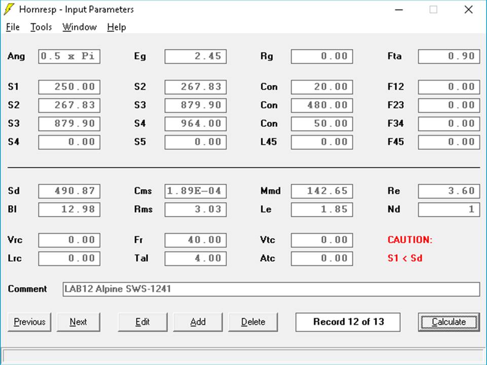
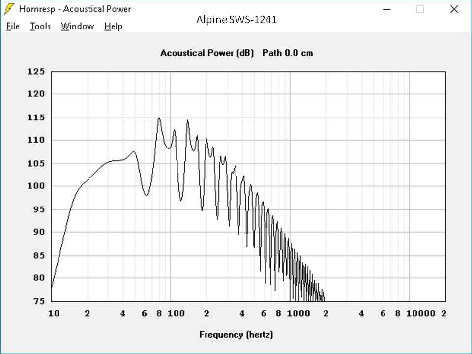
I have modeled the Alpine SWS-1241....
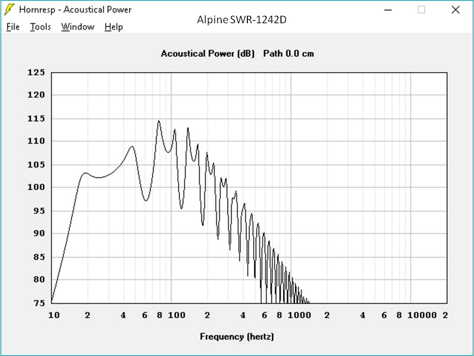
and Alpine SWR-1242D....

I used this as the basic model.....
To me these Alpine look AWAZING - I mean over 100DB @ 1 watt right?
Please tell me I'm wrong? I so want to build a pair of these!
Any help appreciated.
Dear all,
Am new to the horn business and hoping for some guidance please.
I have modeled the Alpine SWS-1241....
and Alpine SWR-1242D....
I used this as the basic model.....
To me these Alpine look AWAZING - I mean over 100DB @ 1 watt right?
Please tell me I'm wrong? I so want to build a pair of these!
Any help appreciated.
Attachments
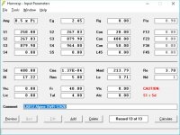
You simulated in 0,5 Space, which means this response is what you get when you put the Sub in a corner. Try double clicking on the "ang" input section to see the differences. Subwoofers usualy are simluated in half space (=2), which corresponds to them standing on the ground. Of course, If you are to put it in a corner, this is right - but watch for the SPL and lower frequencies - how they change while altering ANG.
You get quite a lot of SPL and low end out of a tapped horn compared to a ported Box much smaller comparing the same drivers.
You get quite a lot of SPL and low end out of a tapped horn compared to a ported Box much smaller comparing the same drivers.
A few things:
1. Segments in a TH folded into a rectangular box (like your example) should be modelled as Parabolic (Par) not Conical (Con) segments.
2. For those two drivers you mentioned, you should definitely use the "semi-inductance" option to model them, as their varying inductance is definitely going to have an impact on the response (for more on this, see the "semi-inductance" page on my website). Unfortunately this means that you'll need the extra parameters required for modelling the impact of semi-inductance, and those are not usually quoted. Using the "lossy Le" option is an alternative, but it won't be as accurate.
3. Use Vtc and Atc to include the volume of air in front of the driver's cone in your simulations.
Hi Brian,
Many thanks for this help.
I went back and changed the model from Con to Par. I didn't seem to see any change, but I admit I did not overlay the graphs.
Your semi-inductance write up is very interesting and well constructed. I'd be using the SWR Alpine which has shorting rings and therefore has low and well controlled Le, as I understand it. Therefore, as you've noted in your very helpful write up, should I expect that for the SWR it will have a minimal impact on the modelled response?
I didn't have time to add in the volume of air in front of the driver's cone to the model yet, but happily Alpine includes this in its spec sheets so I'll also do this tonight and look at the change this makes.
Last edited:
Nope, the Alpine driver's semi-inductance parameters definitely need to be considered, based on my experience with the type R 12D2. Sealed alignment, or maybe a re-tuned 4th order BP might work best with them. I'd stay away from higher-order alignments using those drivers.
Attachments
Nope, the Alpine driver's semi-inductance parameters definitely need to be considered, based on my experience with the type R 12D2. Sealed alignment, or maybe a re-tuned 4th order BP might work best with them. I'd stay away from higher-order alignments using those drivers.
Thanks again Brian.
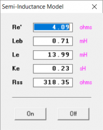
May I assume that the numbers in the thumbnail image are the semi-inductance for the SWR-1242D please? If so, thanks for sharing. I'll plug these in and see how this affects the modelled response.
For some context I guess what led me here was that I wanted some Danley DTS10's but they cost over $10k in Australia. The DTS10 uses LAB12's as I understand it.
This gentleman replaced his dead DTS10 drivers with the Alpine SWR's and reported great results. Theres some great shots in this post too, I do love a pic or two....
Again I assume, the DTS10 is a higher order alignment? Please, don't feel I'm trying to be contrary, really I'm just keen for knowledge. Would you mind helping me understand your recomendation to stay away from the Alpine in this alignment.
Thanks again.
Last edited:
I read that thread. The Eminence LAB12 drivers are very different to the Alpine Type R drivers. And the DTS10 is tuned pretty low. And "good" is a subjective term .
The thread contains no impedance or FR comparison graphs, so it's not possible to say objectively if the replacement of the original drivers with the Type R drivers was an improvement.
.The thread contains no impedance or FR comparison graphs, so it's not possible to say objectively if the replacement of the original drivers with the Type R drivers was an improvement.
Again I assume, the DTS10 is a higher order alignment? Please, don't feel I'm trying to be contrary, really I'm just keen for knowledge. Would you mind helping me understand your recomendation to stay away from the Alpine in this alignment.
Thanks again.
Yes, it's basically a 6th order alignment with a 1/4 WL stub to fill in its 3rd harmonic dip for a bit of extra BW and those guys were switching first to the LMR, then the SWR because they were shredding Lab12s with high SPL down to its ~11 Hz tuning, so a proven 'upgrade'.
Note it needs some EQ, TD, due to being a TH, which is listed on that thread IIRC, then dialed into the system. Anyway, a helpful bunch.
GM
Notwithstanding I take it then that I have used the software correctly and my modeling is valid?
The design should be modelled as a tapped horn, not as a back-load horn. See the Hornresp Help file for details.
Semi Inductance
Thank you David. Amazing to get your help here, thanks! I'll read up and re-model.
Regarding the semi-inductance model information, here is what I get....
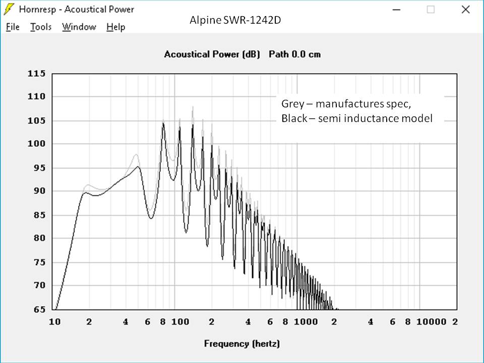
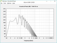
Looks smoother in the pass band, yes?
The design should be modelled as a tapped horn, not as a back-load horn. See the Hornresp Help file for details.
Thank you David. Amazing to get your help here, thanks! I'll read up and re-model.
Regarding the semi-inductance model information, here is what I get....
Looks smoother in the pass band, yes?
Attachments
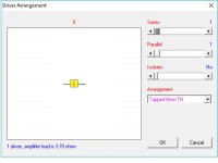
The design should be modelled as a tapped horn, not as a back-load horn. See the Hornresp Help file for details.
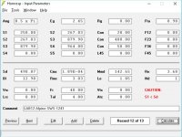
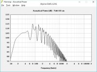
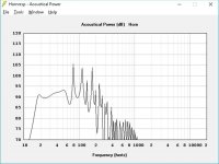
I changed the driver arrangement drop down to tapped horn, hoping I did this correctly?....
Seems smoother again....
Attachments
Last edited:
- Home
- Loudspeakers
- Subwoofers
- Collaborative Tapped horn project