Hi kees,
Someone with practical experience in constructing tapped horns would be in a better position than me to answer your latest questions.
Kind regards,
David
Hi David
Yes that was the plan, I was curieus about this outcome, I think that I have to do myself the folding and so I was start learning sketchup, if there is a other drwan software that is better let me now, this is a ask on the diy,ers not david he have provide me with enough info about hornresp.
some ideas about what I did here with the mivoc I do also like.
regards
I awaiting thanks.
...some ideas about what I did here with the mivoc I do also like...
Hi Kees,
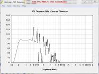
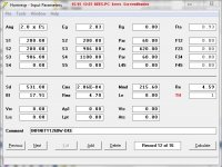
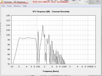
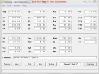
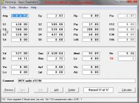
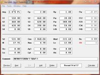
First, At the HR input screen: The picture in Post 3959 show a few mistakes:
You’ve added a loss-less inductor to Le, i.e. to a design that is very sensitive to loss in serie components. Further: The Eg value is set to 20 V = a too high value as x-max(6.3mm) is exceeded (~11 mm at 28 Hz).
You should rely on HR's TS consistency-check when entering numbers..Looks like your numbers are a bit off.
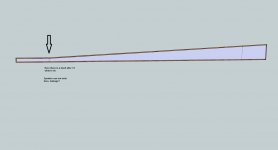
When it comes to your enclosure layout problem: I recommend you to consider a different design:
See the submitted picture..
b
")
Attachments
Hi Bjorno
Hi Bjorno
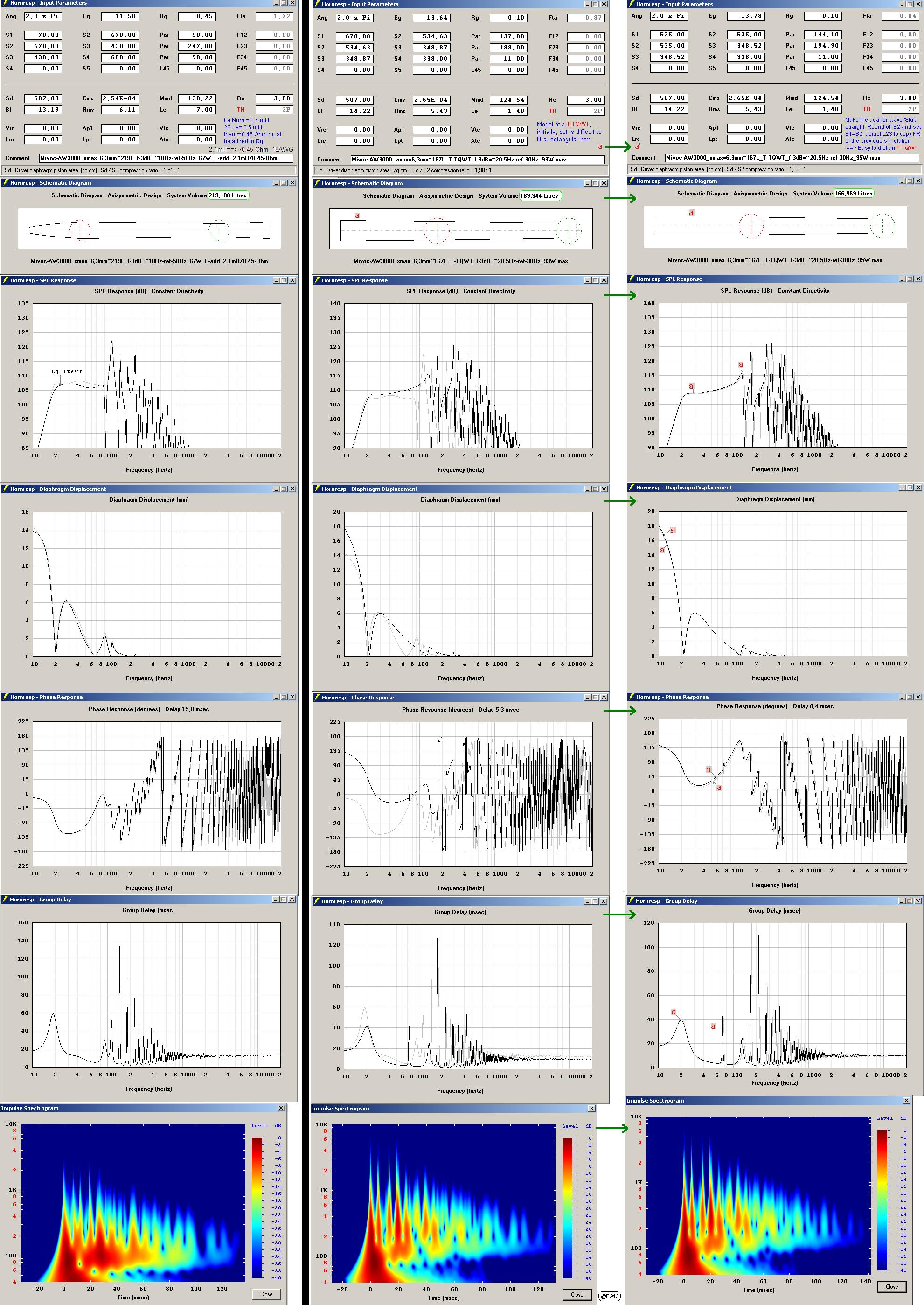
You have use the MAROC design what I have done as a kind of time consumer, I did want nog how strange it is, but further I do nothing with it, do you have use the the same w3000 as I did? you are more succesfull with the T-TQWT
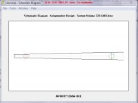
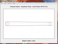
Here is the one I do want to build, it is a tapped horn because this woofer did not well in T-TQWT otherwise I dod go there it looks better and the peak go away with damping let more bandwidth, less sensitivity of a T-TQWT is not a problem in a home.
Do I add the RE and Le to the already excisting speaker value? Yes I have a question left haha, S1 ts straight S2 begin bending, what if the speaker are precisely on that bend, it wil be good, do people then turn over the pipe installing the speaker on the backside keep in mind this when folding?
Thanks for all your help, I be almost be full learned about it.
see pictures about what I already did en will test, my visatons do work fine in a T-TQWT.
regards
kees
Hi Bjorno
You have use the MAROC design what I have done as a kind of time consumer, I did want nog how strange it is, but further I do nothing with it, do you have use the the same w3000 as I did? you are more succesfull with the T-TQWT
Here is the one I do want to build, it is a tapped horn because this woofer did not well in T-TQWT otherwise I dod go there it looks better and the peak go away with damping let more bandwidth, less sensitivity of a T-TQWT is not a problem in a home.
Do I add the RE and Le to the already excisting speaker value? Yes I have a question left haha, S1 ts straight S2 begin bending, what if the speaker are precisely on that bend, it wil be good, do people then turn over the pipe installing the speaker on the backside keep in mind this when folding?
Thanks for all your help, I be almost be full learned about it.
see pictures about what I already did en will test, my visatons do work fine in a T-TQWT.
regards
kees
Hi Kees,
First, At the HR input screen: The picture in Post 3959 show a few mistakes:
You’ve added a loss-less inductor to Le, i.e. to a design that is very sensitive to loss in serie components. Further: The Eg value is set to 20 V = a too high value as x-max(6.3mm) is exceeded (~11 mm at 28 Hz).
You should rely on HR's TS consistency-check when entering numbers..Looks like your numbers are a bit off.
When it comes to your enclosure layout problem: I recommend you to consider a different design:
See the submitted picture..
b
Attachments
Last edited:
You are modeling at 0.5pi. Bjorno is modeling at 2.0pi. Look at bjorno's models at 0.5pi and compare them to your model.
Here we go, but still don,t now how to act as the troat S1 is even square and S2 start to have angle, now I can not install a speaker because hornresp go from center of the speaker as I now, but in schematic it looks that the bend start on the egde of the speaker, do I explane oke?
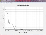
I have now simulated on 2.0 pi see pictures
Attachments
Last edited:
Well I see I can cancel my tapped horn, it will not work with a passive filter as I have seen on some threads, I have hybrides and had plans for use of a 24dB or 18dB passive crossover, I use trafo so I have with 14mH inducion 0.81 ohm resistance, plus 0.6 for the second coil, do eventually a T-TQWT work with a passive filter and how do I fill in the coils, both Re and Le of filter multiplied with the driver induction and resistance?
For as hornresp, speaker coils is parallell with ohms of speaker and coils from crossover is
in serial, also the crossover coils have caps to null and so I don,t now if coil has to be all included.
Some explaning I do like, thanks for all the help.
kees
For as hornresp, speaker coils is parallell with ohms of speaker and coils from crossover is
in serial, also the crossover coils have caps to null and so I don,t now if coil has to be all included.
Some explaning I do like, thanks for all the help.
kees
I am started the advise of Bjorno.
Go to T_TQWT, and so maybe I have to remove then also to a T_TQWT thread?
I did see and test with hornresp that a T-TQWT is more forgiven about the crossover when passive, I deed then minimal 18 dB crossover.
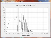
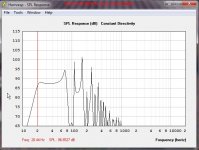
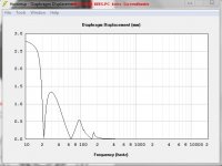
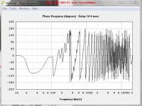
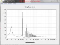
here a the tests, box is also a lot smaller but efficienty is lower 91 dB in stead of 98 dB I think with damping it go wider bandwith.
Bjorno, I have also the sheets from martin, what did you use for simulation tqwt a TL sheet?
thanks all here for the help.
Go to T_TQWT, and so maybe I have to remove then also to a T_TQWT thread?
I did see and test with hornresp that a T-TQWT is more forgiven about the crossover when passive, I deed then minimal 18 dB crossover.
here a the tests, box is also a lot smaller but efficienty is lower 91 dB in stead of 98 dB I think with damping it go wider bandwith.
Bjorno, I have also the sheets from martin, what did you use for simulation tqwt a TL sheet?
thanks all here for the help.
Attachments
Last edited:
Here we go, but still don,t now how to act as the troat S1 is even square and S2 start to have angle, now I can not install a speaker because hornresp go from center of the speaker as I now, but in schematic it looks that the bend start on the egde of the speaker, do I explane oke?
I have now simulated on 2.0 pi see pictures
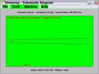
You are using 2.83v/1w for an 8ohm speaker instead of using 2.00v/1w for a 4ohm speaker. Here's a 349 liter, 17 foot long TH that can handle 250 watts at 13mm xmax. Box = 53.25"H x 17.5"W x 31.75"L using 0.75", 19.05mm, 1.905cm stock. The thickness of wood is factored in with Vtc & Atc.
Attachments
Last edited:
You are using 2.83v/1w for an 8ohm speaker instead of using 2.00v/1w for a 4ohm speaker. Here's a 349 liter, 17 foot long TH that can handle 250 watts at 13mm xmax. Box = 53.25"H x 17.5"W x 31.75"L using 0.75", 19.05mm, 1.905cm stock. The thickness of wood is factored in with Vtc & Atc.
Thanks for thinking, I presume that input voltage for 4 or 8 ohm is not as important for me, give onlysome more or les spl, it wil go loud enough.
Buttt a tapped horn wil not work with a normal passive crossover and I do use that because I have no extra bass amp, this I do wil make some day but not now, a T-TQWT is then a better option, less sensitive for coils and resistance.
I think however that hornresp simulate not accurate with a serie coil? because the speaker induction is paralell with ohmic resistance.
thanks again for your sims.
kees
Well my again have some test done with T-TQWT,s, I send back the infinity if not suitable, I did see the mtx is better.
Please let your eyes glide in it and maybe some has a idea about the passive filtering, wot to implement that in hornresp, for example a 18dB octave one, need I to include al the coils or only the one after the capacitor because the first coil has cap to ground.
thanks al and have a nice day/night.
Please let your eyes glide in it and maybe some has a idea about the passive filtering, wot to implement that in hornresp, for example a 18dB octave one, need I to include al the coils or only the one after the capacitor because the first coil has cap to ground.
thanks al and have a nice day/night.
Attachments
-
 MTX audio rt12-04-1.jpg50.8 KB · Views: 61
 -
 INFINITY1260W-4.jpg69.4 KB · Views: 41
 -
 INFINITY1260W-5.jpg53 KB · Views: 48
 -
 INFINITY1260W-2.jpg58.5 KB · Views: 54
 -
 INFINITY1260W-1.jpg55.4 KB · Views: 44
 -
 MTX audio rt12-04-5.jpg43.2 KB · Views: 41
 -
 MTX audio rt12-04-4.jpg65.3 KB · Views: 40
 -
 MTX audio rt12-04-3.jpg47 KB · Views: 54
 -
 MTX audio rt12-04-2.jpg67.2 KB · Views: 57
 -
 INFINITY1260W-3.jpg48.9 KB · Views: 36
Last edited:
if you want to model crossover networks, you have to export your hornresp simulation to akabak - there you can model more stuff.
I´d strongly advise not to use passive x-overs with subwoofers.
Unfortanely I can not run akabak in 64 bit windows 7, plus I have no experience with akabak scripts, I did mean a T-TQWT simulation inclusief a 80 Hz low pass filter I have trafo,s coils with have max 0.4 ohm or lower, it looks like evertyhing tapped is not suitable for passive filtering.
regards
kees
Why do you think a tapped horn is less suitable for passive filtering than a direct-radiation closed box? That´s not the case. The Impedance gets in your way either way and when dealing with pro sound levels of energy, you need massive coils, which are so exepnsive - you can get a simple active crossover for the money and sometimes even a extra amp-channel für the top speakers.
Of course there are a lot of subs around which have passive x-overs inside. And depending on the usage and power levels, it "works somehow".... But if you want to "do it right", aktive filtering in pro sound subwoofers is the only right way to go.
If you want it done passive, keep in mind you need a impedance compensation in most cases to hit the x-over point correctly and not to introduce resonances (thats another reason why passive crossovers get more complicated and expensive..).
If you want to ran akabak in 64 Bit windows, try some virtualiser like vmware and install a 32 bit windows into it. There are free alternatives, look up wikipedia fir vmware. I even tried reactos (freeware os, which tries to re-build windows from scratch, very promising) a year ago and hornresp worked fine in there.
Hi Sabbelbacke
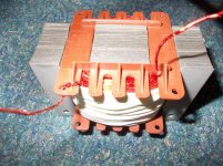
I make my own coils, soon I have aluminium wire insulated like copper wire but very low resistance.
see this it did costs 20 euro and can adjust with airgap, 22mH max with gap = 4mm 12mH min (open U) 0.78 ohm 0.8 mm wire. if no gap it go 56mH.
I make my own coils, soon I have aluminium wire insulated like copper wire but very low resistance.
see this it did costs 20 euro and can adjust with airgap, 22mH max with gap = 4mm 12mH min (open U) 0.78 ohm 0.8 mm wire. if no gap it go 56mH.
Attachments
Last edited:
I make my own coils,
Hi kees,
I run 'Oracle WM Virtualbox in Windows' with no problems...
Am I right: Your are not designing for PA use, but for home?.and is a true Electronics DIY guy like I consider myself to be.
My ~BW of design experiences is up to 22 Ghz but peaking below 2 GHz and of course at the Audio frequencies..close to 50 Years.
I think you're quite capable to design flawless passive filters for any, even for sub use XO'd down to 30 Hz because you have no problems to practically wind any coil based inductor with or without a core, with or without an air-gap to a blameless functional reactive power component like I have done for more than 45 Years.
You probably too have a lot of copper in possession with various dimensions ( I have more than 30 kg shaped to inductance coils / 50kg not yet used and tons of transformers that you can dismantle the ordinary use and instead change to be used as coils in speaker designs.
Nearly all(must be >99%) the suggested flat FR designs I've posted are for to be used with an ordinary Plate Amp of some sort with a passive filter if not an active is already incorporated, thus there is no need to compensate the FR BW using an EQ for a single system component like a sub, neither requiring a signal-delay compensation of the Main-Speakers or for additional flanking(lateral) subs if in use.
Here are summed impressions of what I noticed when reading trough all the Post since my last one:
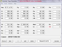
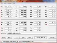
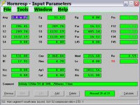
In Post #3907 you are showing an HR input screen of Eminence Kappa Pro 12A published TS that have been correctly entered with an additional Inductor effectively increasing the Le value to 5 mH.
This is allowed when in the reality implementing a first order series LP filter loss-less TF to modify the BW and Amplitude/Phase of the simulation:
In practice;
To implement this design can only be executed by using an active filter but if a passive filter is targeted: The always existing loss-value must be added to Rg in Hr but never to Re.
I posted in #3918 a simulation of correctly entered TS parameters and in Post #3962 I even added
..AS A HINT..
Inductance to the input screen for the Mivoc driver to the very odd design in order to show how its correctly done, thus by not screwing up the TS parameters.
To make a serious post: Always do a check of entered TS parameters:
They should be very similar to the 'Advertised Numbers' Just double-click the entered Sd number..
If the shown fundamental TS parameters deviates too much:
Something is wrong: Either are some of the given TS not reliable or the entered, but be sure that when entered correctly:
HR always makes a consistency check of the input parameters.
Noob mistakes are allowed but there must be a limit.... huh
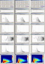
Now, I have decided that from post #3911 there are systematical errors in all of the posted OP HR input screens and IMO also affecting the annoying row of singly posted unintelligibly-labeled 'loose-leaf system-graphs':
You're never sure to which of the input screen they are related to if there are more than one system with or without different drivers.
Why not merge the graphs into a single row so it's easy to scroll the suggested design up and down?
Don’t despair:
Try another simulation using the MTX-RTS12-04 driver I find interesting, remember to put your coil-loss into the Rg label:b
Hi Bjorno
Ja oke, you are right I am some sloppy guy, I do jump to one and then another in a learning process. I see you are a real electronics man, do you work with transmitters? I have a sensitivity for microwave transmitters, I live in a clean environment for this, I now a guy who have his house full of electronics, go everywhere to buy from bankrupted company,s and radio meetings, incredible what he have, so much that he has no place anymore for himslefs, old scoops, spectrum analizers some really expensive go into the microwaves, parts, he is a high end man for audio.
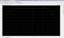
I am a amp man, I do design amps, but I need speakers also, I have now dipoles and open baffles who sounds wonderfull but the bas need some more power (no pressure), the linkwitz dipoles go low, very low that is a fact, I have build in my hybrid amps a shelf filter for 6 dB correction also passive because the mid and high is also on that same amp, works like a sharm, see picture after correction...
Oke, I have seen your hints however I can not read the pictures, are to small to read maybe there is a way to download or so in original form.
The TS parameters I do always like you say, never did it the other way, also I have the martin sheets where also is a consistancy check sheet who I always use, I have limp and a box to measure but need to build a amp in it that is now done and go build that thing.
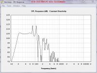
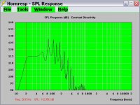
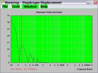
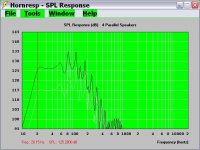
The mic amp is also most ready, I do need that stuff for boxes, I have done measurements on my own system and that is quite oke see picture.
I have only the infinity driver and i did found easy horn sheet here, that is a better way to get a beginning, the hornresp sliders are quite time consuming but fun it like I am in a casino try to win a price.
Oke, what I do need to now is when I have say a 24 db passive filter, with for 4 ohm a coil 14mH then cap then 7.8 mH and cap, or when 18dB after 7.8mH no cap what to do? do I have also input al that mH stuff 21.8mH or only the coil where is no cap crossed, it simulate not very good if I do so high induction with simulation.
So I put coil resistance in Rg label? mine is 0.8 ohm so I put that in, this I did now now, until now thanks, in martins sheets it is easy to do, nice stuff..
I have found in China aluminium wire isolated like copper, you now aluminium has very low resistance and that it sounds bad what some high end goeroes tell I do not believe she use silver wire with teflon..
Can you make your pictures readable for me, bigger, then I can look (what I did) to see what you have, I also have read and look to other threads of you because you a experiented guy what concerns the T-TQWT and such and I am a electronics guy, I did not much with speakers but will do now for a change.
How nice that in the old days efficienty was born, you now why, see the old Jenssen radiator, everyone do make old stuff also the TQWT is old from mister Voight.
Thanks for all the advise, I go look, test, and learn without al that post, I think that I already get on the good path..
regards
kees
Ja oke, you are right I am some sloppy guy, I do jump to one and then another in a learning process. I see you are a real electronics man, do you work with transmitters? I have a sensitivity for microwave transmitters, I live in a clean environment for this, I now a guy who have his house full of electronics, go everywhere to buy from bankrupted company,s and radio meetings, incredible what he have, so much that he has no place anymore for himslefs, old scoops, spectrum analizers some really expensive go into the microwaves, parts, he is a high end man for audio.
I am a amp man, I do design amps, but I need speakers also, I have now dipoles and open baffles who sounds wonderfull but the bas need some more power (no pressure), the linkwitz dipoles go low, very low that is a fact, I have build in my hybrid amps a shelf filter for 6 dB correction also passive because the mid and high is also on that same amp, works like a sharm, see picture after correction...
Oke, I have seen your hints however I can not read the pictures, are to small to read maybe there is a way to download or so in original form.
The TS parameters I do always like you say, never did it the other way, also I have the martin sheets where also is a consistancy check sheet who I always use, I have limp and a box to measure but need to build a amp in it that is now done and go build that thing.
The mic amp is also most ready, I do need that stuff for boxes, I have done measurements on my own system and that is quite oke see picture.
I have only the infinity driver and i did found easy horn sheet here, that is a better way to get a beginning, the hornresp sliders are quite time consuming but fun it like I am in a casino try to win a price.
Oke, what I do need to now is when I have say a 24 db passive filter, with for 4 ohm a coil 14mH then cap then 7.8 mH and cap, or when 18dB after 7.8mH no cap what to do? do I have also input al that mH stuff 21.8mH or only the coil where is no cap crossed, it simulate not very good if I do so high induction with simulation.
So I put coil resistance in Rg label? mine is 0.8 ohm so I put that in, this I did now now, until now thanks, in martins sheets it is easy to do, nice stuff..
I have found in China aluminium wire isolated like copper, you now aluminium has very low resistance and that it sounds bad what some high end goeroes tell I do not believe she use silver wire with teflon..
Can you make your pictures readable for me, bigger, then I can look (what I did) to see what you have, I also have read and look to other threads of you because you a experiented guy what concerns the T-TQWT and such and I am a electronics guy, I did not much with speakers but will do now for a change.
How nice that in the old days efficienty was born, you now why, see the old Jenssen radiator, everyone do make old stuff also the TQWT is old from mister Voight.
Thanks for all the advise, I go look, test, and learn without al that post, I think that I already get on the good path..
regards
kees
Attachments
Hi kees,
Am I right: Your are not designing for PA use, but for home?.and is a true Electronics DIY guy like I consider myself to be.
b
I do only home stuff, my plan was/is high end amps for possible bussiness, there are more rich people who do not now what to do with all that mony, mybe I do, so I need good boxes for demonstrations, I do not PA systems. I have artrosis and do not work, maiby for my own and go live in warm country like spain and making amps, I do not go make loudspeakers this stay as hobby.
Now I did try your advise and I think now it get more the way I want.
I have use only the last free coil 18dB low pass on the output there is no coil.
suprising the infinity wil do in a T-TQWT and so I do not tapped horn, the T-TQWT it is smaller and I have this infinity woofer who is good made with good qts of 0.37.
Thanks bjorno I have thanks to you make a quick school, PS I have not yet a program to merge pictures, so comes later.
regards.
kees
Attachments
Last edited:
Hi kees52,
I like your inductor.
To see bjorno's pictures in full size: click on the lower left hand corner (see attached picture) in his pictures.
Regards,
Thanks
I can expand the pictures here but also the go bigger but also then I can not read the hornresp input, it is to blurred.
The coils, ye I need a winding machine (DIY) you now some drawns, I did it be hand, 46 minutes of windings and a complete lame hand.
thans for help.
kees
- Home
- Loudspeakers
- Subwoofers
- Collaborative Tapped horn project