Ok, i know it can be a bit confusing to look at all those numbers, but it is really simple.
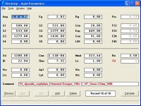
Here, I've adapted those numbers into something slightly easier. It's basically close to the very same numbers, but I've cut off one step. Now, the first number (S1) is the area of the beginning of the horn, I changed it to 500 cm2, because that means the area would have to be 50 x 10 cm, 50 cm wide, and 10cm deep. The S2 and Con fields tell you where the center of the woofer cone should be, I put in 20 cm here, as 10 cm's seems very little for a 18", it's close enough to not matter that much if it's a cm or two off, but put the cone as close as possible to the beginning of the horn.
The S2 and S3 combined with Exp, thell you where the front of the woofer meets the horn from the back of the woofer, or vice versa. Exp is the length of the horn in cm, S2 and S3 is still the area of the horn at those specific places. S3/internal width = depth. so: 1279cm2/50cm=25,58cm deep at S3.
S4 is the very end of the horn, so S3 to S4 combined with the last Con tell us how the horn should be from the woofer cone nearest the end of the horn, to the end of the horn. so it should be 91cm long, and expand from 50x25,58cm at the cone, to 50x28,6cm at the mouth of the horn.
The easiest way to know how your horn should be buildt, is to draw on a piece of paper, a figure with straight lines, the beginning would be 10mm wide, the end would be about 28,5mm wide, the length should be 560mm . You should be able to fit the complete design in a finished box measuring 52,4 x 91,4 x 144,4 cm, on a drawing this would be about 52,5 mm x 91,5 mm x 144,4 mm.
This is using 22mm thickness material of your choice, most people in the know, prefer ply on their horns, not MDF.
I tried changing the last value of con among a variety of numbers, if you get the end result within 10 cm of what you design, it should not alter the frequency response significantly.
I am a complete n00b at Tapped horns, so if anyone want to correct me, feel free to do so.
Edit:
Oh, and remember to put in some bracers, the materials will flex at the widest and longest areas.
Attachments
Last edited:
Hi KaffiMann,
Nephylum seems to just be fishing for a complete enclosure design for the "best" available driver, the 19Ov.2 being just one of many") . As you seem to be interested in the gap between theory and practice, and as I'm the one who posted the 4-section tapped horn model for nephylum in his "tuba vs taphorn?" thread as an example for a 4-section v. a 3-section model, I think I'll comment:
. As you seem to be interested in the gap between theory and practice, and as I'm the one who posted the 4-section tapped horn model for nephylum in his "tuba vs taphorn?" thread as an example for a 4-section v. a 3-section model, I think I'll comment:
- Without having the actual T/S parameters we are just rolling the dice (e.g.: this driver in the model is quite sensitive to Le, and that value is not provided by the manufacturer). If the initial simulation leads to the purchase of a driver, or if one is on hand, this driver should be measured, and the model readjusted accordingly.
- When comparing models Ang/Eg should be identical.
- The 4-section model simply gives more freedom of design than the 3-section model, particularly when looking at a tapped horn that (most likely, because of the horn length) cannot be build as a simple single fold.
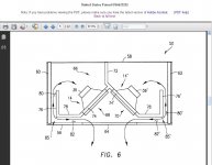
- L12 has a strong impact on the impulse response, and should be kept as short as possible (without negatively impacting the first dip in the passband); e.g.: (looking at the patent drawing) the DTS-20 has no L12, the driver feeds the horn directly through a coupling chamber, i.e.: S1 is S2. Another practical example is described in detail by screamerusa in his "LIVE SOUND Specific Tapped Horn thread...".
- The model should include the effects of speaker mounting and coupling, if possible, thus Ap1/Lpt/Vtc/Atc should be used (even if they don't make much of a difference). Obvioulsy, for a quick-and-dirty leave 'em out, and use the 3-section, but don't cut up a couple of sheets of baltic birch from those numbers.
- To me the model is only a starting point for an initial evaluation, which leads to a drawing, which leads to a new model, and so on until a desired degree of agreement between model and drawing has been reached. Additionally, Hornresp has the ability to export an Akabak script. This makes it easier to get started in Akabak and to refine the model beyond what is possible in Hornresp. These iterations can really cut down the failure rate.
- Then I would build a test box. For a box this size (and weight) I recommend 18mm (3/4") plywood for the box and dividers, and 12mm (1/2") for bracing between dividers. With an internal box width of 50cm (20") I would use bracing between all dividers. The pictures in the AVS forum thread on the Danley DTS-10 show an appropriate construction, looks like 3/4" baltic birch throughout. For a test box I recommend OSB.
Prior to all of the above the desired end results and usage expectations as well as the available enclosure dimensions, quantities and locations should be defined in detail.
Regards,
Nephylum seems to just be fishing for a complete enclosure design for the "best" available driver, the 19Ov.2 being just one of many
. As you seem to be interested in the gap between theory and practice, and as I'm the one who posted the 4-section tapped horn model for nephylum in his "tuba vs taphorn?" thread as an example for a 4-section v. a 3-section model, I think I'll comment:- Without having the actual T/S parameters we are just rolling the dice (e.g.: this driver in the model is quite sensitive to Le, and that value is not provided by the manufacturer). If the initial simulation leads to the purchase of a driver, or if one is on hand, this driver should be measured, and the model readjusted accordingly.
- When comparing models Ang/Eg should be identical.
- The 4-section model simply gives more freedom of design than the 3-section model, particularly when looking at a tapped horn that (most likely, because of the horn length) cannot be build as a simple single fold.
- L12 has a strong impact on the impulse response, and should be kept as short as possible (without negatively impacting the first dip in the passband); e.g.: (looking at the patent drawing) the DTS-20 has no L12, the driver feeds the horn directly through a coupling chamber, i.e.: S1 is S2. Another practical example is described in detail by screamerusa in his "LIVE SOUND Specific Tapped Horn thread...".
- The model should include the effects of speaker mounting and coupling, if possible, thus Ap1/Lpt/Vtc/Atc should be used (even if they don't make much of a difference). Obvioulsy, for a quick-and-dirty leave 'em out, and use the 3-section, but don't cut up a couple of sheets of baltic birch from those numbers.
- To me the model is only a starting point for an initial evaluation, which leads to a drawing, which leads to a new model, and so on until a desired degree of agreement between model and drawing has been reached. Additionally, Hornresp has the ability to export an Akabak script. This makes it easier to get started in Akabak and to refine the model beyond what is possible in Hornresp. These iterations can really cut down the failure rate.
- Then I would build a test box. For a box this size (and weight) I recommend 18mm (3/4") plywood for the box and dividers, and 12mm (1/2") for bracing between dividers. With an internal box width of 50cm (20") I would use bracing between all dividers. The pictures in the AVS forum thread on the Danley DTS-10 show an appropriate construction, looks like 3/4" baltic birch throughout. For a test box I recommend OSB.
Prior to all of the above the desired end results and usage expectations as well as the available enclosure dimensions, quantities and locations should be defined in detail.
Regards,
Hello tb46
Thank you for responding to my post, this certainly clarifies a few things.
I did ask if he had the opportunity to measure the thiele small parameters first, as I could not find any info on that myself. If the only issue is the Le of the driver, this can easily be increased to match the horn better, lowering it may be a different issue.
On the plans i have seen laying about, of other designs, the S2 value has been marked just before the cap of the cone, this is why I suggested 20 centimeters instead of 10. At any rate, i told him to put the woofer as close to the beginning as possible, I also tried changing these values to see if they make too much of a difference, as I always do.
I do not see any reason to use 4 sections in modelling a tapped horn like this, i see very little or no difference in the number of sections modelled, if the expansion is constant. If you change the expansion however, there is a difference. As I see it, you can make any number of folds you want, as long as you stay true to where the air from the beginning of the horn, meets the air moved by the other side of the cone, and keep the distance from the woofer to the mouth as planned. You will probably loose some efficiency, but the frequency response should be the same. All double folded tapped horn calculations would be completely useless in hornresp if you where to depend on the number of parts you can have in the program. There will be too many bends to do them justice anyway.
I may have picked up things the wrong way here, but feel free to comment. This is a forum after all
(I also suggested to use 22mm thickness material, in case you did not notice.)
Oh, and I may have helped him help himself, but i do not do those things directly, that just makes a lot more work.
Edit:
Nephylum, if you look at the frequency response of that tapped horn, you will see that below a certain frequency, the horn does not make much sound at all. But you will make the cone of the woofer move, alot. the hp filter is to stop the woofer from making wasted movement. Easing the load on both amplifier and woofer.
Last edited:
The change in IR shown in HR comes from the changes in the FR, mainly above 100Hz. It doesn't really do a lot for the bandwidth the sub will actually be used in. You can check this out for yourself in AkAbak, as it allows you to band limit the IR graphs.L12 has a strong impact on the impulse response, and should be kept as short as possible (without negatively impacting the first dip in the passband); e.g.: (looking at the patent drawing) the DTS-20 has no L12, the driver feeds the horn directly through a coupling chamber, i.e.: S1 is S2.
The DTS-20 has an L12. It is the distance from the center of the driver/or port, in relation to the horn path, to the throat of the horn. Which would be the point of the wedge here. The small Throat Chamber between the driver and horn does not change this.
The real advantage of moving the front tap position is to alter the low corner response. Increasing the distance can improve the the lowend response on a driver with a weak motor.
S2 is where the center of the driver or tap is located in relation to the horns path.On the plans i have seen laying about, of other designs, the S2 value has been marked just before the cap of the cone, this is why I suggested 20 centimeters instead of 10.
---
I do not see any reason to use 4 sections in modelling a tapped horn like this, i see very little or no difference in the number of sections modelled, if the expansion is constant.
In order to build a TH properly you need to use all 4 sections, as you must set the flare rate for the sections before, and after the rear tap independently for the best response. See the patent app. If you are just after a simple TP, then you don't have to worry about it.
S2 is where the center of the driver or tap is located in relation to the horns path.
In order to build a TH properly you need to use all 4 sections, as you must set the flare rate for the sections before, and after the rear tap independently for the best response. See the patent app. If you are just after a simple TP, then you don't have to worry about it.
Ah, I see. But in Volvotreter's and Cowan's designs they did not pay any attention to that, how much does it really affect the end result?
S2 is a lot of places defined as the distance from cone to throat, I have always calculated it as near center of cone to throat, thank you for confirming this. It seems my 20 cm calculation on the 18" was a good assumption.
Best regards.
Hi KaffiMann,
quote: "This is a forum after all"
I just wanted to clarify where this came from, please, help nephylum all you can. I have no problems at all with your post, just a different viewpoint on some details.
Hi Soho54,
quote: "The DTS-20 has an L12."
I agree, that's one way to look at it. That's how I often end up with relatively short L12 values. Good point about the weak motor low end response.
Regards,
quote: "This is a forum after all
"I just wanted to clarify where this came from, please, help nephylum all you can. I have no problems at all with your post, just a different viewpoint on some details.
Hi Soho54,
quote: "The DTS-20 has an L12."
I agree, that's one way to look at it. That's how I often end up with relatively short L12 values. Good point about the weak motor low end response.
Regards,
Are you talking about dialing in the flare rates?Ah, I see. But in Volvotreter's and Cowan's designs they did not pay any attention to that, how much does it really affect the end result?
If so, it can make a very big difference. Especially if you are trying to get as much bandwidth as possible. If you are only after the BP like FRs, then it isn't as big a deal.
Well, it IS a big deal with the right driver/horn combo. It is also important to try and vary some of the aspects of the horn calculation, to be sure there is not big enough of a difference if you're a little bit off when actually building.
...
But what I wrote was:
"I do not see any reason to use 4 sections in modelling a tapped horn like this, i see very little or no difference in the number of sections modelled, if the expansion is constant."
I mean that if the flare (and therefore also the total length) of the horn is the same as when calculating up to S4, why should you use S5?
Isn't S5 only usable if you have varying flare rates?
And why would you have varying flare rates after the driver? If you expand the flare near the driver, there is more even gain than if you expand the flare after the driver.
Edit:
I may be expressing myself wrongly, but I do hope you get my question.
Last edited:
Yeah, something is getting lost, but it isn't a big deal.
Yes, if you are only using a simple single conical flare rate there is no need to use S5. You are just stuck with what you get.
With a single flare rate you give up some sensitivity, or bandwidth. Unless you have just the right driver with the right parameters to work with your horn at that low corner. It happens, but not often.
Hi,
I have finally made it through this thread and cannot help but wonder if somebody has done some work on trying to tame the response with Helmholz resonators similar to the design example by E. Jakulis on a TQWT (tapered quarter wave tube)?
It seems that a similar technique would be almost necessary to optimize this design.
This is from way back on page 101.
I am looking for any information available concerning the use of helmholtz resonators to reduce the impact of unwanted higher order modes in transmission lines / QWT's. I have the E. Jakulis article and have picked up the odd tidbit around the place.
I am intending to research this area in detail but I would like to survey any existing documents before committing saw to wood.
I would appreciate any wisdom / experience you might care to offer, as well as pointers to any relevant resources.
TIA,
Keith Arnold
I was looking at this earlier today.
Just use this: frequency = ( ( 0.5 * c ) / PI ) * SQRT( Port Area / (Port length * Cavity Volume ) )
along with AkAbak, and you are good to go.
You have to account for port end correction as well. You can use the normal back of the hand factors, but the best bet would be to put the ports in an area that can be reached, so that you can install the ports, and later trim them to the appropriate length. Like you would a BP enclosure.
Last edited:
I was looking at this earlier today.
Just use this: frequency = ( ( 0.5 * c ) / PI ) * SQRT( Port Area / (Port length * Cavity Volume ) )
along with AkAbak, and you are good to go.
You have to account for port end correction as well. You can use the normal back of the hand factors, but the best bet would be to put the ports in an area that can be reached, so that you can install the ports, and later trim them to the appropriate length. Like you would a BP enclosure.
Thanks for your reply!
I am quite familiar with helmholtz resonators (and am getting the hang of TQWTs). I have Hornresp, a heap of generic design programs, and the MJK worksheets. Do I need AkAbak to model this, perhaps?
My first trial project will be just as you say with pull out/cut/replace ports for messing around.
I guess what I am really after is some feedback from those who may have built or pondered such things in the past. Where along the line is the best place for the resonators? Does the resonator Q matter? Is the whole thing just more trouble than it is worth?
There seems to have been some interest in this idea in the past but it seems to have dropped dead in the last few years.
So, has it been tried and abandoned, or is it still out there as an idea waiting for someone to bring it up to date (like TLs themselves and even tapped horns)?
Your thoughts, please !
Keith Arnold
AkAbak is the only easily acquired program I know of that will handle this properly.
You asked about placement, and Q. Yes, they both matter, and the only way to simulate how they will affect the FR is to model them together.
I think the idea was abandoned when DSL came out with the newer THs that didn't use them. The fact that AkAbak was needed to simulate them didn't help either. Most people would also only want a very narrow notch taken out, and that is easier to do with a single closed end pipe, tapped into the horn near the throat.
In a more BP type enclosure it could be beneficial.
If you can handle HR you can export your TL into AkAbak, and just add the HRCs there. There are several AkAbak how-to's around now, so a bit of reading, and a few hours tinkering should be enough to get you working in AkAbak.
AkAbak is the only easily acquired program I know of that will handle this properly.
You asked about placement, and Q. Yes, they both matter, and the only way to simulate how they will affect the FR is to model them together.
I think the idea was abandoned when DSL came out with the newer THs that didn't use them. The fact that AkAbak was needed to simulate them didn't help either. Most people would also only want a very narrow notch taken out, and that is easier to do with a single closed end pipe, tapped into the horn near the throat.
In a more BP type enclosure it could be beneficial.
If you can handle HR you can export your TL into AkAbak, and just add the HRCs there. There are several AkAbak how-to's around now, so a bit of reading, and a few hours tinkering should be enough to get you working in AkAbak.
Thanks again for your reply!
Looks like it is time to get to grips with AkAbak......
There is a discussion starting on MJK's Quarter Wave group about using multiple closed stubs at the throat to cancel out higher modes, so maybe the time is right for this subject to get a second look?
It is probably more a full range issue now though, especially as TH design progress seems to have rendered such frills unnecessary for modern subs.
If I get any interesting results I will start a thread in the FR forum.
Meantime, I still welcome comments from those who may have tried modelling or building horns or TLs or variants, which use resonators or stubs to control higher modes in their enclosures.
TIA!
Keith Arnold
1/4 Wave Resonators
Hi blakkshepeaudio,
Hi Keith, it is nice to see somebody digging into this subject, and AkAbak will definitely be needed for simulation.
I don't think that there is any evidence, that "...TH design progress seems to have rendered such frills unnecessary for modern subs...". It is evident though, that from a manufacturers viewpoint 1/4 wave resonators are a substantial additional expense. If you look at the discussion of the DTS-10 sub on the AVS Forum you will see that this sub (one of the "newest") still suffers from substantial peaks that could be tamed by physical means, and then the use of electronic means would not only be easier, it would also be more effective. 1/4 wave resonators could be added from the outside terminating in the throat region. The same holds true for the TH-Spud for expample.
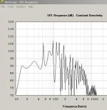
I'll attach a typical simulation of the SPL response of such a "new" tapped horn (dual driver, similar to TH-Spud and/or DTS-10).
Regards,
Hi blakkshepeaudio,
Hi Keith, it is nice to see somebody digging into this subject, and AkAbak will definitely be needed for simulation.
I don't think that there is any evidence, that "...TH design progress seems to have rendered such frills unnecessary for modern subs...". It is evident though, that from a manufacturers viewpoint 1/4 wave resonators are a substantial additional expense. If you look at the discussion of the DTS-10 sub on the AVS Forum you will see that this sub (one of the "newest") still suffers from substantial peaks that could be tamed by physical means, and then the use of electronic means would not only be easier, it would also be more effective. 1/4 wave resonators could be added from the outside terminating in the throat region. The same holds true for the TH-Spud for expample.
I'll attach a typical simulation of the SPL response of such a "new" tapped horn (dual driver, similar to TH-Spud and/or DTS-10).
Regards,
Attachments
Hi blakkshepeaudio,
Hi Keith, it is nice to see somebody digging into this subject, and AkAbak will definitely be needed for simulation.
I don't think that there is any evidence, that "...TH design progress seems to have rendered such frills unnecessary for modern subs...". It is evident though, that from a manufacturers viewpoint 1/4 wave resonators are a substantial additional expense. If you look at the discussion of the DTS-10 sub on the AVS Forum you will see that this sub (one of the "newest") still suffers from substantial peaks that could be tamed by physical means, and then the use of electronic means would not only be easier, it would also be more effective. 1/4 wave resonators could be added from the outside terminating in the throat region. The same holds true for the TH-Spud for expample.
I'll attach a typical simulation of the SPL response of such a "new" tapped horn (dual driver, similar to TH-Spud and/or DTS-10).
Regards,
Thanks for your reply!
Yes, I always believe that things should be as well sorted as possible physically before the fun starts with electronics.
My suggestion that "...TH design progress seems to have rendered such frills unnecessary for modern subs...". really reflected my observation that few people seem to comment on it as a serious problem. I have read others say that an LR4 will cut the sub off before it gets to the problem frequencies that you can't do much about anyway.
This may even be true, which is one reason why I am pursuing this line of questioning in the first place. Has somebody tried this and was it worth the trouble. There is at least one manufacturer using this technique although I have no indication of how successful it is.
Anyhow, all correspondence is very gratefully received, and I will be investigating this and related phenomena in coming weeks.
Thanks again,
Keith Arnold
Hi,
Take a look at this thread:
http://www.diyaudio.com/forums/subwoofers/145993-jl-8w7-home-design.html
Regards,
It looks like JL Audio discovered the tapped horn, and patented it:
An externally hosted image should be here but it was not working when we last tested it.
It looks like JL Audio discovered the tapped horn, and patented it:
Ported loudspeaker enclosure
Ahhh ha ha ha ha ha....... gotta love that.
I'd say from the look of the double... that the cubo is definitely off limits.... This looks to be more hybrid than tapped, but the concepts are still the same. Wonder how DSL will deal with this?
So... no more cubo's.... or hybrid reflex/short horns -- those are patent infringing..... and have been since 2003....
Attachments
Last edited:
- Home
- Loudspeakers
- Subwoofers
- Collaborative Tapped horn project