Vas the easy way
Hi Jean-Michel
The way I do Vas is to use children's modeling clay. It sticks to the cone without much trouble. But it requires a scale to determine the mass of the clay.
The way I used to do it is by taping coins to the cone of the driver. All countries keep their coin weights to quite strict tolerances. You merely need to find the mass of the coins you are using and add enough to effect the mass of the cone assembly by approximately 25%. (Which also works and does not require a scale to measure the weight.) The tape used is not really much of an inaccuracy.
Once you know the Vas then you can do some proper modeling in Hornresponse.
Mark
Re: jm_kzo's Beyma TH
Hi Oliver,
can I do that with "poor man" simple voltmeter ?
I assume that at low frequencies like this the DC (or do you say AC) position should work. I do not have anything else handy...
tb46 said:Hi Jean-Michel,
Have you checked that your amplifier is driving a correct signal into your speaker? If the bottom of the amplifier output is not flat.....
Regards,
Hi Oliver,
can I do that with "poor man" simple voltmeter ?
I assume that at low frequencies like this the DC (or do you say AC) position should work. I do not have anything else handy...
Sabbelbacke said:Another simple thing, but maybe becaus it´s so simple one doesn´t see it:
is the mic calibrated and accurate?
Hi Saddelbacke,
no the mic is not calibrated per say, but it is meant to be flat...
It is a Panasonic WM-61A electret with a Wallin schema. I boought the PCB from an online shop in the UK... They now do have a new version of the PCB and the associated component set on sale... I was contemplating buying this in case I had some wiring wrong/wrong components, but at the same time my mic has measured my current set up down to this kind of frequencies without looking too bad...
Maybe I need to do this again just to check how low it goes.
Re: Vas the easy way
Hi Mark,
I did not think Vas made a difference in HR. Does it ?
My kids are now too old for clay") .
.
How do you attache the coins to the cone ? This is the bit I am struggling with.
mwmkravchenko said:Hi Jean-Michel
The way I do Vas is to use children's modeling clay. It sticks to the cone without much trouble. But it requires a scale to determine the mass of the clay.
The way I used to do it is by taping coins to the cone of the driver. All countries keep their coin weights to quite strict tolerances. You merely need to find the mass of the coins you are using and add enough to effect the mass of the cone assembly by approximately 25%. (Which also works and does not require a scale to measure the weight.) The tape used is not really much of an inaccuracy.
Once you know the Vas then you can do some proper modeling in Hornresponse.
Mark
Hi Mark,
I did not think Vas made a difference in HR. Does it ?
My kids are now too old for clay
.How do you attache the coins to the cone ? This is the bit I am struggling with.
Re: Re: Vas the easy way
I believe I've mentioned at least 3 times now that an accurate vas measurement is pretty important. Additionally, most of the other parameters will be wrong if vas is wrong. Cms, rms, bl and mmd are all derived using vas.
FWIW though, based on the impedance graph I still think there's an air leak.
jm_kzo said:
Hi Mark,
I did not think Vas made a difference in HR. Does it?
I believe I've mentioned at least 3 times now that an accurate vas measurement is pretty important. Additionally, most of the other parameters will be wrong if vas is wrong. Cms, rms, bl and mmd are all derived using vas.
FWIW though, based on the impedance graph I still think there's an air leak.
BTW, assuming the specs you actually measured are correct (they probably are) and assuming the manufacturer's specs for SD and BL can be trusted (SD is probably ok, BL is anybody's guess), using winisd to backfill for unknown vas, it calculates 21.77 liters.
But again, if vas is in question in the first place there's really no reason to believe the manufacturer's spec for BL is any better.
Taking these shaky assumptions to their conclusion reveals that if vas really is 21.77 liters, that is not the cause of this issue.
But again, if vas is in question in the first place there's really no reason to believe the manufacturer's spec for BL is any better.
Taking these shaky assumptions to their conclusion reveals that if vas really is 21.77 liters, that is not the cause of this issue.
Post #3182_voltmeter
Hi Jean-Michel,
Yes, a simple AC voltmeter should be sufficient for measurements in the range you are looking for. You are not looking for microvolt accuracy or anything like that. And by the way, it is good practice to check your drive voltage at the driver if for no other reason then as a "sanity check".
I don't believe that your speakers are so far of their factory specification that the parameters are at fault, and, you used a simple single fold design that fits the hornresp model quite well, so this box should work unless we are all overlooking something (wouldn't be the first time).
Regards,
Hi Jean-Michel,
Yes, a simple AC voltmeter should be sufficient for measurements in the range you are looking for. You are not looking for microvolt accuracy or anything like that. And by the way, it is good practice to check your drive voltage at the driver if for no other reason then as a "sanity check".
I don't believe that your speakers are so far of their factory specification that the parameters are at fault, and, you used a simple single fold design that fits the hornresp model quite well, so this box should work unless we are all overlooking something (wouldn't be the first time
).Regards,
jm_kzo said:
Sorry, but you lost me here...
The T&S parameters I have measure with SW are as follows :
The box net volume (all removed) is 15.5l ........
The vent is 58mm inside diameter and 40mm long. The measured tuned frequency is 62.2Hz.
Greets!
I was wondering if the power source and/or the sound card and/or the mike was flat to a very low frequency. Some begin rolling off as high as 100 Hz.
OK using these specs I let HR work back to a 24.91 L Vas and then it calc'd a 19.32 N/A BL. This just made the response slightly more under-damped, so can't account for your measurement anomalies.
Hmm, if the box is empty except for negligible padding, this is the box's gross volume (Vb). Net Vb would be after the driver, vent, any bracing, etc. has been deducted. Anyway, assuming a ~15.2 L net Vb and a 5.8 cm dia. vent 4 cm long, HR sims ~93 Hz and MJK's MathCad software ~89 Hz Fb (which I consider the more accurate of the two, not that the difference would be audibly obvious), so it appears that you have some measurement issues that need to be resolved.
GM
Coins plus tape = known mass
Hello Jean-Michel
My french is sad to say the least. Ruban is close I hope. But pretty sure it is an incorrect use of the word. So a picture is worth all the french I don't know! I was kicked out of french almost 30 years ago!
http://content.answers.com/main/content/img/getty/6/3/AA027163.jpg
Mark
Hello Jean-Michel
My french is sad to say the least. Ruban is close I hope. But pretty sure it is an incorrect use of the word. So a picture is worth all the french I don't know! I was kicked out of french almost 30 years ago!
http://content.answers.com/main/content/img/getty/6/3/AA027163.jpg
Mark
just_a_guy W6-1139
Hi just_a_guy,
Here is another attempt at modelling the W6-1139 with your parameters. This time I added a front chamber with a small port.
The overall volume is a little higher than yours and the SPL is a hair smoother, but still basically the same. I added a small (1mH/.05Ohm) inductor just to have it in the model. This smoothens the small bump after the first dip, but does not do much at this value.
Regards,
Attachments
Re: just_a_guy W6-1139
Thanks for the suggestions, all comments are appreciated and suggestions will be studied and considered. But it's going to be at least a couple of weeks before I work my way up to that point - and probably more like a couple of months. Before I even think about a revised edition I am going to test the first one thoroughly to validate or disprove the assumptions I made when designing it.
First, a quick note about size. The box is somewhere near 65L internally, initially the size was chosen somewhat arbitrarily as a best guess as I have no verifiably accurate method of choosing an appropriate Vb. Later on however, it struck me that the BIB calculator would probably yeild a fairly appropriate Vb (and tuning frequency) for any given driver so I tried my driver parameters in the BIB calculator and it says 67L with a tuning about an octave below driver fs which seems reasonable to me (especially since it's basically the same as what I built) but ymmv. So the size is not going to change unless I find an incredibly compelling reason to do so and I haven't found it yet.
1st test - finding it's limits. This test is well underway. The only 4 ohm amp I have is a car stereo amp so I "installed" (and I use the term very loosely) a stereo in my car. As you may suspect it needed a bit of frequency response tailoring to sound right in a car. First impressions are incredibly positive. For a 6.5 inch driver with 23 hz tuning this thing is LOUD. I could go on but I don't have an spl meter to back up my impressions so I won't bother.
2nd test - more accurate groundplane measurements. The ones I did were done as fast as possible on mushy ground on a cold and windy day just to get an idea. I intend to do better on a nice calm spring day, possibly even on a large concrete parking lot late at night. We still haven't had a single really nice day yet.
3rd test - possibly most important - listening tests in a regular room. I've got active xo and parametric eq so I'm not worried about frequency response in the least, just need to know if I like how it sounds.
Only after I collect this information will I look at what needs to change and how best to accomplish those changes, so it's probably not going to happen anytime soon. I can guarantee I won't be using inductors though, they are just too expensive.
tb46 said:Hi just_a_guy,
Here is another attempt at modelling the W6-1139 with your parameters. This time I added a front chamber with a small port.
The overall volume is a little higher than yours and the SPL is a hair smoother, but still basically the same. I added a small (1mH/.05Ohm) inductor just to have it in the model. This smoothens the small bump after the first dip, but does not do much at this value.
Regards,
Thanks for the suggestions, all comments are appreciated and suggestions will be studied and considered. But it's going to be at least a couple of weeks before I work my way up to that point - and probably more like a couple of months. Before I even think about a revised edition I am going to test the first one thoroughly to validate or disprove the assumptions I made when designing it.
First, a quick note about size. The box is somewhere near 65L internally, initially the size was chosen somewhat arbitrarily as a best guess as I have no verifiably accurate method of choosing an appropriate Vb. Later on however, it struck me that the BIB calculator would probably yeild a fairly appropriate Vb (and tuning frequency) for any given driver so I tried my driver parameters in the BIB calculator and it says 67L with a tuning about an octave below driver fs which seems reasonable to me (especially since it's basically the same as what I built) but ymmv. So the size is not going to change unless I find an incredibly compelling reason to do so and I haven't found it yet.
1st test - finding it's limits. This test is well underway. The only 4 ohm amp I have is a car stereo amp so I "installed" (and I use the term very loosely) a stereo in my car. As you may suspect it needed a bit of frequency response tailoring to sound right in a car. First impressions are incredibly positive. For a 6.5 inch driver with 23 hz tuning this thing is LOUD. I could go on but I don't have an spl meter to back up my impressions so I won't bother.
2nd test - more accurate groundplane measurements. The ones I did were done as fast as possible on mushy ground on a cold and windy day just to get an idea. I intend to do better on a nice calm spring day, possibly even on a large concrete parking lot late at night. We still haven't had a single really nice day yet.
3rd test - possibly most important - listening tests in a regular room. I've got active xo and parametric eq so I'm not worried about frequency response in the least, just need to know if I like how it sounds.
Only after I collect this information will I look at what needs to change and how best to accomplish those changes, so it's probably not going to happen anytime soon. I can guarantee I won't be using inductors though, they are just too expensive.
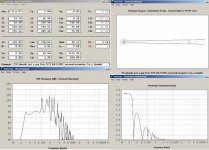
Hey Oliver, here's a good example of why I don't want to rush things and why it's hard to tell what a measurement is actually saying unless great care is taken to extract the best results (IOW what you want to see).
Below is an example of a groundplane measurement I snagged today. I had to get it in quick because the weather channel says it's going to start raining this afternoon and last til the end of forever. This measurement was done in my hard packed but wet gravel driveway (the last measurement I posted was on the lawn) with a different amp and this time the box is standing up (last time it was lying flat on the ground). Also, mic distance was closer this time, 2m, since I was only able to get about 5m away from the car and 10m away from the house. Additionally the mouth was well stuffed with fibreglass insulation this time. The measurement looks better but it sounds muffled so the stuffing will need adjustment.
Anyway, this is a lot closer to what I was originally expecting to see - other than the nasty gash at 80 hz which doesn't want to go away - and why it's best not to rush things before a full analysis is complete.
Below is an example of a groundplane measurement I snagged today. I had to get it in quick because the weather channel says it's going to start raining this afternoon and last til the end of forever. This measurement was done in my hard packed but wet gravel driveway (the last measurement I posted was on the lawn) with a different amp and this time the box is standing up (last time it was lying flat on the ground). Also, mic distance was closer this time, 2m, since I was only able to get about 5m away from the car and 10m away from the house. Additionally the mouth was well stuffed with fibreglass insulation this time. The measurement looks better but it sounds muffled so the stuffing will need adjustment.
An externally hosted image should be here but it was not working when we last tested it.
Anyway, this is a lot closer to what I was originally expecting to see - other than the nasty gash at 80 hz which doesn't want to go away - and why it's best not to rush things before a full analysis is complete.
Yes, by fiddling with the sliders you can deal with it, but it won't be anything like what your stated design goals are. Regardless, like Mark, I just view it as a good place to put an XO, especially since a typical ~8 ft high ceiling will broaden the notch down into the 70s.
GM
GM
GM said:Yes, by fiddling with the sliders you can deal with it, but it won't be anything like what your stated design goals are.
GM
I'm aware there is only one best design for any given driver but I'm doing the best I can with my limited skillset and I'm really trying hard to do a good job. The only tools I have to work with are this thread, pictures of measurements (and there's only precious few so far), and sliders. I have no math skills as you know, and only a general understanding of horns.
WRT my stated design goals, they are pretty general. Large enough to hopefully get close to reactance annulled (by pure luck - but that's all that I have), tuned about 1 octave below fs, fairly flat response up to and including at least the first of the two "problem" peaks, and as loud as possible all things considered.
Any other issues I may have mentioned here or elsewhere don't seem to matter much at all so far.
I should probably take this opportunity to take a few weeks to study some more to try again to figure all this out before proceedingwith the sliders.
Anyways, thanks for your comments, always appreciated.
You're welcome!
Hmm, there's only one technically ideal BP/horn/TH alignment AFAIK, so ideally the driver's specs will match up with the desired BW, but once you move away from it there's typically many other 'best' alignments, they just have less usable gain BW than the ideal one.
I thought small size was a primary goal. If not, then never mind.
GM
- Home
- Loudspeakers
- Subwoofers
- Collaborative Tapped horn project