fb said:
The amp modules I plan to use offer 300W into 8 ohms and 600W into 4 ohms.
How much bigger does a tapped horn get for 2 drivers relative to 1 driver? That might be what I'm missing (avoiding).
Generally speaking - it doubles in size.
rolandong said:Using Eminence Definimax 4015lf, 40x28x22.5 dimensions (HxDxW),
do you think below is worthy of some sawdust?
A few minor changes might get rid of the dip at 130 Hz - whifh is harder to deal with than a spike. With everything else as you have it, lengthen l3 to 27 cm. I attached my version with a few tweaks as done in Hornresp. Throat and mouth areas seem to produce as much SPL as you can get. You'll run out of excursion before you run out of power handling - excursion at 48 Hz with 600 watts is over 15 mm (xlim). Applying some damping material in the throat should tame the spike at 130 Hz, the spike at 210 Hz may be outside your desired passband so it may not matter. The notch at 270 Hz should also be outside the passband - again - not an issue.
All that being said - If I had a Definimax 4015LF to play with and needed a PA sub - I'd build that box or something very similar - it certainly seems worthy of sawdust to me.
Attachments
Re: JM's Beyma 10G40 TH (bass MIA)
That's great news!!
I'd suspect your in-room measurements first. I know that the software all agreed, but the speaker and microphone were in the same spot in room each time, so there may be a room mode there that alters the response. I know that where I measure in the room has an affect on the response I get. I definitely saw differences between the initial close-mic measurements I did and the 1M groundplane measurements. I have a larger calibration resistor ordered so I can do 28.3V/10M measurements in the future.
jm_kzo said:Guys,
I must that I might need to publically apologize and eat humble pie...
Though I do not trust my hears, today I tried to *listen* instead of *measure*...
After extracts of LOTR, Star Wars and The Incredibles, I think my unit definitely does bass below 60Hz...
I am not sure what is wrong yet or if I overcome the issues of my design and/or build by the HT amp settings and cross-over, but the tapped horn was definitely shaking the room.
--snip--
I hope to keep you posted soon.
That's great news!!
I'd suspect your in-room measurements first. I know that the software all agreed, but the speaker and microphone were in the same spot in room each time, so there may be a room mode there that alters the response. I know that where I measure in the room has an affect on the response I get. I definitely saw differences between the initial close-mic measurements I did and the 1M groundplane measurements. I have a larger calibration resistor ordered so I can do 28.3V/10M measurements in the future.
just a guy said:---snip---
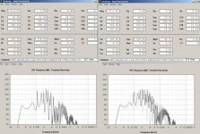
Here's some ground plane measurements taken outside today. It was quite windy and the ground is wet and mushy with spring thaw. The laptop was placed on the ground, mic facing towards the box, about 7m away (I was limited by the length of my cables). Measured 4 times, just to be sure. I guess the 30 hz dip isn't going to be a problem, but the dip at 80 hz suggests a bit of a redesign is in order. Should be easy enough to fix next time around.
---snip---
Looks like you're on the right track. Looks like you need to lengthen the distance from the driver to the mouth - that should bring the bottom of the trough up to near the passband efficiency. The damping tames the spikes pretty well, but fixing a significant trough like that is tough to do.
I guarantee that your amp does not double it's maximum power into half the load impedance.fb said:The amp modules I plan to use offer 300W into 8 ohms and 600W into 4 ohms.
A really bad amp might give similar power into half impedance.
A poor amp could give 50% more into half impedance.
A good amp will give at least 70% more into half impedance.
A great amp will give at least 80% more into half impedance.
Your 600W into 4r0 amplifier may give anywhere between 600W into 8r0 and 330W into 8r0.
littlemike said:
Looks like you're on the right track. Looks like you need to lengthen the distance from the driver to the mouth - that should bring the bottom of the trough up to near the passband efficiency. The damping tames the spikes pretty well, but fixing a significant trough like that is tough to do.
I agree that moving the driver further down the line would help the dip at 80 hz but there's only so far you can go with that before you start worsening the dip at 30 hz. This issue is going to require a total redesign, but nothing too drastic. The throat, flare rate, both driver tap positions (and therefore the entire folding), stuffing (lining) implementation will all change slightly for the second one. Some of the assumptions I made while designing the first one were off, it shouldn't be any trouble at all to get the next one much flatter in response. Ruler flat response is not really a priority though, even the TH-SPUD for example is about +/- 5db through the passband (but yeah, 10 db dips like I have now are pretty extreme and will be fixed).
The good news is that the prototype isn't necessarily garbage, if I do better on the other 3 they should all blend well together.
Post #3130
Hi just_a_guy,
I looked at your cad drawing a little bit closer, and noticed that the last section of the horn leading up to the mouth does not expand like the rest, also the distance of the center boards at the 180 degree turns does not allow for even expansion around the bends. I doubt that any of that makes a big difference, but you may take a note for your next prototype. Thanks for the information, keep it coming.")
Regards,
Hi just_a_guy,
I looked at your cad drawing a little bit closer, and noticed that the last section of the horn leading up to the mouth does not expand like the rest, also the distance of the center boards at the 180 degree turns does not allow for even expansion around the bends. I doubt that any of that makes a big difference, but you may take a note for your next prototype. Thanks for the information, keep it coming.
Regards,
Attachments
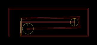
The cad man ended up using volvotreter's folding method, I wanted as little as possible to do with the folding so I wasn't really watching what he was doing but during the physical panel layout I did take the time to make sure that it was constantly expanding through all the bends. The bends might not be perfect but I'm pretty sure they are good enough.
WRT the last bend and the non expansion near the end, see the attached drawing, in particular the panel I added in red (it's supposed to be 5/8, same as the rest of the material). This step was part of the design to perserve the final expansion but in the end I didn't bother with it as I can't imagine it having any practical effect.
If you can figure out the best way to model this send me the hornresp inputs. I wasn't really going to bother but since you're doing the work anyway...
WRT the last bend and the non expansion near the end, see the attached drawing, in particular the panel I added in red (it's supposed to be 5/8, same as the rest of the material). This step was part of the design to perserve the final expansion but in the end I didn't bother with it as I can't imagine it having any practical effect.
An externally hosted image should be here but it was not working when we last tested it.
If you can figure out the best way to model this send me the hornresp inputs. I wasn't really going to bother but since you're doing the work anyway...
Post #3130, #3169
Hi just_a_guy,
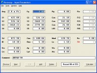
I don't think I know the best way to model this or any other tapped horn, but as you're asking I'll attach my hornresp input screen for your Post #3130, as well as an attempt at fixing the big dip in the model around 96Hz (your measurement about 86Hz) as suggested by littlemike in Post #3164.
Remember, it's worth what you paid for it. Thanks for doing the hard work.
Regards,
Hi just_a_guy,
I don't think I know the best way to model this or any other tapped horn, but as you're asking I'll attach my hornresp input screen for your Post #3130, as well as an attempt at fixing the big dip in the model around 96Hz (your measurement about 86Hz) as suggested by littlemike in Post #3164.
Remember, it's worth what you paid for it. Thanks for doing the hard work.
Regards,
Attachments
Ok, thanks, that's actually surprisingly close to what I guessed so I guess my translation from design to wood isn't as inaccurate as I thought. The difference between modelled and measured then, is probably due to construction error resulting in the throat being just a bit bigger than planned. (1 mil deviation from the plans is pretty significant in the throat area.)
BTW, if you want to do an accurate model that you can correlate to the frequency response measurements I posted you have to use my measured parameters. Using the factory specs is a recipe for disaster. My measured fs is way higher than factory spec and my vas is way lower, even after being broken in. It's different enough to be pretty significant.
I had a quick look at your proposed changes. That's not exactly the way I'd do it but it's certainly moving in the right direction. Regardless, the overall size and shape is going to remain the same, this is going to be a matching set of 4.
Oh, did I forget that too? It's pretty important... Here's the estimated inputs for the horn from after the folding session, very close to your measured results. Also note the measured driver parameters which ended up being way closer to littlemike's measured parameters than factory spec. (littlemike's were measured with a woofer tester so may or may not be more accurate than mine)
I wasnt' going to bother including these inputs as I didn't think they were a completely accurate representation of the final product, but since your numbers are so close to mine it must be close.
An externally hosted image should be here but it was not working when we last tested it.
I wasnt' going to bother including these inputs as I didn't think they were a completely accurate representation of the final product, but since your numbers are so close to mine it must be close.
Beyma 10G40 TH, bass still missing
Guys,
I have done my tapped horn as air tight as possible and glued everything (bye bye experiments)...
I have measured again my T&S parameter as well as I could (bar Vas, but as far as I understand it does not really matters here)...
I have tried other drivers of the same make and model...
And no improvement... Measure still loks pretty much the same
The frequency responce wether in mouth, one meter away or in room is nothing like it should be... Ok, granted my measurement could be wrong and I have not done "ground plane measurement" yet, but 1)I will struggle with free space, 2)I should have bass in the room.
More worringly, my impedance measurement is way way off, with a first peak way too small and a lot smaller than the 2 next ones...
I cannot figure out what is wrong, but I must say that I start to lose hope and faith and I am tempted to go back to basic BR design...
I suspect there is something wrong with T&S parameters as the length of my vent is massively different to the one I have to get the tuning frequency (measured). WinISD says it sould be 8.6cm, I had to go down to 4cm (yes, 4!!!) to get the tuning frequency right.
I hate not to understand and I hate failure, but maybe it was a too big bite to swallow for me.
Anyway, if you have ideas, please fire.
OK, if you're satisfied that the TH is airtight, then the only other thing that comes to mind short of grossly inaccurate T/S specs is that the signal measurement chain rolls off down low since the response is falling with the impedance as opposed to DSL's TH-50 where the damped impedance peak defines its LF corner frequency (knee).
WRT WinISD or any other basic freeware box calculator for that matter, none are noted for being very accurate calculating vent length since they assume the box is an ideal Helmholtz resonator. That said, that is further off than typical, so list the design details for us to compare in more accurate programs.
GM
HI GM,
Sorry, but you lost me here... I am fairly new to all this thing and maybe I need a bit moer explanations, sorry.
The T&S parameters I have measure with SW are as follows :
FS : 59.81
Qts : 0.375
Qms : 10.524
Qes : 0.389
Le : 0.032mH
L1 : 1.548
R1 : 37.723
Re : 6.6 (measured with ohm-meter)
The other parameters are from the Beyma spec :
SD : 330cm²
XMax : 0.6cm
BL : 17.90
Vas : 33l (I know I could/should measure Vas, but this added mass method thing that requires glueing stuff to teh cone puts me off).
The box net volume (all removed) is 15.5l with 3 walls covered with rockwhool (quite thin).
The vent is 58mm inside diameter and 40mm long. The measured tuned frequency is 62.2Hz.
I hope you can spot something.
Many thanks for your help and interest.
GM said:OK, if you're satisfied that the TH is airtight, then the only other thing that comes to mind short of grossly inaccurate T/S specs is that the signal measurement chain rolls off down low since the response is falling with the impedance as opposed to DSL's TH-50 where the damped impedance peak defines its LF corner frequency (knee).
Sorry, but you lost me here... I am fairly new to all this thing and maybe I need a bit moer explanations, sorry.
GM said:WRT WinISD or any other basic freeware box calculator for that matter, none are noted for being very accurate calculating vent length since they assume the box is an ideal Helmholtz resonator. That said, that is further off than typical, so list the design details for us to compare in more accurate programs.
GM
The T&S parameters I have measure with SW are as follows :
FS : 59.81
Qts : 0.375
Qms : 10.524
Qes : 0.389
Le : 0.032mH
L1 : 1.548
R1 : 37.723
Re : 6.6 (measured with ohm-meter)
The other parameters are from the Beyma spec :
SD : 330cm²
XMax : 0.6cm
BL : 17.90
Vas : 33l (I know I could/should measure Vas, but this added mass method thing that requires glueing stuff to teh cone puts me off).
The box net volume (all removed) is 15.5l with 3 walls covered with rockwhool (quite thin).
The vent is 58mm inside diameter and 40mm long. The measured tuned frequency is 62.2Hz.
I hope you can spot something.
Many thanks for your help and interest.
- Home
- Loudspeakers
- Subwoofers
- Collaborative Tapped horn project