Sounds like your having fun.
The phase shift looks a bit excessive over the audio band. I would have to analyse the circuit but you should measure after the input filter (although that won't make a huge difference). Limited slewing of the VAS (C15) might be worth looking at.
I agree, the phase shift is too excessive and I think a slight redesign is in order. I'm going to follow the suggestions laid out in the E.Cherry paper I linked in the previous post and see what results I get.
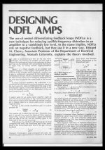
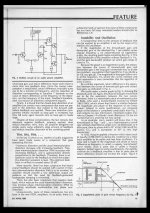
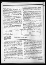
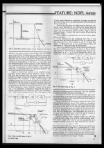
Just in case the link dissapears in the future, here is the article attached as a group of images.
Attachments
Cherry's NDFL is a very different animal.
I strongly suggest you don't try to implement NDFL until after you have learned a lot lot lot more about how amplifiers work.
His NDFL has been discussed in this Forum, but some prefer the TMC & variants which they say are more stable.
I strongly suggest you don't try to implement NDFL until after you have learned a lot lot lot more about how amplifiers work.
His NDFL has been discussed in this Forum, but some prefer the TMC & variants which they say are more stable.
Cherry's NDFL is a very different animal.
I strongly suggest you don't try to implement NDFL until after you have learned a lot lot lot more about how amplifiers work.
His NDFL has been discussed in this Forum, but some prefer the TMC & variants which they say are more stable.
Agreed. After seeing the schematic of his amp in the link below with its multitude of nested loops and current sources; it's far too much to try and do while I'm only just beginning to learn about discrete design.
His feedback method you described is also explained in the link:
http://www.linearaudio.nl/linearaudio.nl/Miscellaneous/cherry ndfl amp.pdf
He uses the formulas Rf1*Cf1 = Rf2*Cf2 & Rf3 = 2*Rf2 to calculate the feedback network.
This corresponds to the values you recommended as:
Rf1 = 6.8k
Rf2 = 15k
Cf2 = 5uF
If I follow Cherry's method to the letter, then 6.8k*Cf1 = 15k*5uF therefore Cf1 must be 11uF - this is a wee bit on the low side, but for the sake of science I tried it.
I simulated and prototyped with your values as well as the following:
Rf1 = 15k
Cf1 = 1000uF
Rf2 = Rf1
Cf2 = Cf1
The results were the same for both sets of values in both the sims and in reality. The low frequency square waves were still rather triangular. It seems though that his theory is sound, so I'll continue trying with this.
I'll try your other recommendations over the weekend to see what can be done about the rather large phase shift at high frequencies.
Thanks again for taking the time to help. I really appreciate all the assistance that I can get.
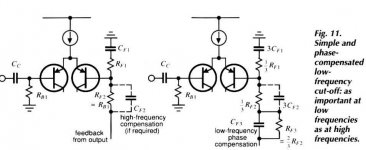
Fig10 does not show the compensated feedback that I have been referring to.
That rf2 is still the NDFL feedback.
I have a copy of another article showing the extra rf3//C it is in fig2 of the pdf.
I'll try to attach it here. It's too big @ 2.6MB
I'll try compression and see if it comes in under the 1MB limit for a zip.
That rf2 is still the NDFL feedback.
I have a copy of another article showing the extra rf3//C it is in fig2 of the pdf.
I'll try to attach it here. It's too big @ 2.6MB
I'll try compression and see if it comes in under the 1MB limit for a zip.
the administrator binned my post !The administrator has specified that you can only edit messages for 30 minutes after you have posted. This limit has expired, so you must contact the administrator to make alterations on your message.
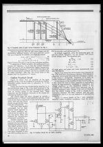
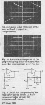
Dr Cherry - phase corrected NFB
Cherry tells us that Rb1=Rf2+Rf3
and that Rf3=2*Rf2
therefore we get
Rf2= 1/3*Rb1 and Rf3=2/3*Rb1
He also tells us that Rf3*Cf3 = 2*Rf1*Cf1
and from that we get Cf3=Cf1*Rf1/Rf2
eg.
with Cc=1uF, Rb1=45k, Cf1=100uF, Rf1=680r
then we get Rf2=15k, Rf3=30k, Cf3=4u5F with an F-3dB = 3.5Hz.
Cherry tells us that Rb1=Rf2+Rf3
and that Rf3=2*Rf2
therefore we get
Rf2= 1/3*Rb1 and Rf3=2/3*Rb1
He also tells us that Rf3*Cf3 = 2*Rf1*Cf1
and from that we get Cf3=Cf1*Rf1/Rf2
eg.
with Cc=1uF, Rb1=45k, Cf1=100uF, Rf1=680r
then we get Rf2=15k, Rf3=30k, Cf3=4u5F with an F-3dB = 3.5Hz.
Attachments
Last edited:
Cherry tells us that Rb1=Rf2+Rf3
and that Rf3=2*Rf2
therefore we get
Rf2= 1/3*Rb1 and Rf3=2/3*Rb1
He also tells us that Rf3*Cf3 = 2*Rf1*Cf1
and from that we get Cf3=Cf1*Rf1/Rf2
eg.
with Cc=1uF, Rb1=45k, Cf1=100uF, Rf1=680r
then we get Rf2=15k, Rf3=30k, Cf3=4u5F with an F-3dB = 3.5Hz.
To calculate the F-3dB point are you using (1/(2pi*Rf1*Cf1))+(1/(2pi*Rf3*Cf2)) ?
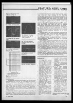
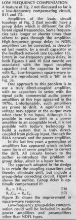
Here's some screen grabs from the link in post #63 for anyone else that wishes to read about the subject.
15k/680 (gain = 23) is a bit too much gain for what i need for this project but is perfect for later when I will come to build a power amp. That being said however, it never hurts to try something, so I'll still see what it does.
Attachments
I just tested the amplifier with the cherry style feedback vs regular feedback.
Test #1 Cherry style feedback Gain = 23
Rf1 = 680
Cf1 = 100uF
Rf2 = 15k
Cf2 = 4.7uF
Rf3 = 30k
Test #2 Cherry Style feedback. Gain = 3.2
Rf1 = 6.8k
Cf1 = 100uF
Rf2 = 15k
Cf2 = 47uF
Rf3 = 30k
Test #3 Regular style feedback. Gain = 3.2
Rf1 = 6.8k
Cf1 = 100uF
Rf2 = 15k
I tested each circuit with a 100Hz square wave and measured the difference between the max peak (PKmax) and min (PKmin) of each corner of the square wave. The volume was adjusted so that Pmax in each test was 2V.
Results:
Test#1
PKmax = 2V
PKmin = 1.5V
Test#2
PKmax = 2V
PKmin = 1.5V
Test#3
PKmax = 2V
PKmin = 1.5V
did you check the input against the output?
Maybe the input has the slope.
Thats a good point. I'll check that tomorrow morning and report back.
Do you mean directly on the signal generator output? Because if i recall correctly, it puts out a reasonably square wave even at low frequencies.
at the input to the amp and at the output from the amp.
That way you see the change that the amp makes.
It's the comparison that you look at.
Absolute values are very difficult to get right and often can be very misleading.
Compare whenever you measure, if at all possible.
That way you see the change that the amp makes.
It's the comparison that you look at.
Absolute values are very difficult to get right and often can be very misleading.
Compare whenever you measure, if at all possible.
Success!
So it turns out that the root of the problem was the high pass filter on the input. After swapping out the 1uF input cap for a 22uF a big improvement was seen. I then tried two 1000uF caps back to back to make a 500uF bipolar and a further improvement was observed.
I tried both traditional feedback and the Cherry style feedback. There was a big improvement with the Cherry feedback.
Feels good.
AndrewT, That Cherry LF compensation is really a neat trick, thanks for the tip.
The only side effect I can see is the potential increase in offset voltage as a result of the higher Rf and Ibos contribution.
If you make the total Rf the same for Cherry's approach versus just one C then the difference isnt quite as dramatic, still really neat, thanks again
-Antonio
The only side effect I can see is the potential increase in offset voltage as a result of the higher Rf and Ibos contribution.
If you make the total Rf the same for Cherry's approach versus just one C then the difference isnt quite as dramatic, still really neat, thanks again
-Antonio
You have trimmed the 47k at the input (Rb1) to minimise output offset?
Now filter the input so that the "corrected" amplifier only has to process the required bandwidth, i.e. put back in the LF passive filter that you need to give you the sound you require.
The overall effect is now a good amplifier response and a higher input impedance combined with a slightly lower noise contribution from the Rf1 value.
It seems the Cherry idea works. I like it and have used it in three amplifiers, so far, even chipamps.
You have trimmed the 47k at the input (Rb1) to minimise output offset?
Output offset is below 5mV before the output cap and 0V after it. I'd say that's good enough.
Now filter the input so that the "corrected" amplifier only has to process the required bandwidth, i.e. put back in the LF passive filter that you need to give you the sound you require.
The overall effect is now a good amplifier response and a higher input impedance combined with a slightly lower noise contribution from the Rf1 value.
Done. A 4.7uF input cap with 47k of input impedance seems to be a good compromise between LF filter frequency and square wave performance.
It seems the Cherry idea works. I like it and have used it in three amplifiers, so far, even chipamps.
It does seem to work. Thank you for bringing it to my attention, it's a tool that I will make great use of in the future.
My next task is to sort out HF feedback in order to fix the phase problems at the other end of the amplifiers bandwidth.
Circuit now seems to meet all necessary parameters
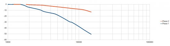
I now have what appears to be a circuit which is stable at all frequencies (even without the feedback cap C15) and exhibits good phase behaviour at both ends of its bandwidth.
The phase diagram depicts both the before and after slopes. Red obviously being the after.
It's been a long day, I think I'll have a beer
Attachments
4.7uF is too big as an input capacitor.
That puts LF signal across the NFB capacitor.
The passive filter at the input must be at a higher frequency than the NFB roll-off.
The NFB roll-off RC is 680r * 100uF = 68ms
The input filter must be less than 68/sqrt(2) i.e. < 48ms
With input resistance set to 44k then the input cap must be less than 1.1uF, not 4.7uF
Note, 44k is the theoretical trimmed value to match the -IN & +IN source resistances.
47k//680k ~ 44k
Oh. Ignore all the above I thought you still had the high gain version !
R12 = 6k8. This seems too high for a pre-amp.
What about reducing the feedback values by a factor of 10?
Last edited:
Next step.
The base current into Q10 must be set up to exactly match the sum of the base currents into Q4 + Q3.
This ensures that the collector currents of the LTP are equal.
This is done by selecting an hFE and/or an Ic for Q10 such that the base current sum comes out to be equal.
BTW, you may find it easier to source bc560c, rather than bc547c
Last edited:
R12 = 6k8. This seems too high for a pre-amp.
What about reducing the feedback values by a factor of 10?
Do you mean that the gain is too high? I can reduce it if would give better performance.
Wouldn't I then have to reduce the input impedance by a factor of 10?
The NFB roll-off RC is 680r * 100uF = 68ms
The input filter must be less than 68/sqrt(2) i.e. < 48ms
With input resistance set to 44k then the input cap must be less than 1.1uF, not 4.7uF
Would it be a problem if I increased the input cap to 10uF? This gives much nicer low frequency square wave performance than 4.7uF.
Feedback RC = 6.8k*100u = 680mS
Input RC = 10uF*47k = 470mS
QUOTE=AndrewT;3139181]Next step.
The base current into Q10 must be set up to exactly match the sum of the base currents into Q4 + Q3.
This ensures that the collector currents of the LTP are equal.
This is done by selecting an hFE and/or an Ic for Q10 such that the base current sum comes out to be equal.
[/QUOTE]
Done. I did this by adjusting Q10 Ic by increasing R13, is this a correct way to do it?
I also increased R9 to 3k as the sims showed better distortion figures than when it was 1k. Any ideas as to why this is?
BTW, you may find it easier to source bc560c, rather than bc547c
I have a bunch of BC546C and a few BC556C, that I have been using for testing but I plan to get some KSC1845F & KSA992F which are almost as cheap as the 547/557 transistors and appear to have better specs and just as available as the 560/550 transistors.
I know this might change some of the other component values but that's no big problem.
I'll be using BCM857BS/BCM847BS for the input as per Calvin's recommendation in post #38 and probably some 2SA1381/KSA1381 for the output.
Thanks again
Attachments
Last edited:
- Status
- This old topic is closed. If you want to reopen this topic, contact a moderator using the "Report Post" button.
- Home
- Source & Line
- Analog Line Level
- Class A preamp: please critique my circuit and give me helpful suggestions.