That's right.
C2 increases the feedback at higher frequencies and is required for stability with this kind of circuit.
With R1 at 100 ohm you shouldn't have any major problems with different loadings. When testing the amplifier always scope the true output (left side R1) as well as across the load.
On a practical level you could try a load of 10k in parallel with say 470pf and same again using 1000pf (1nf).
Also test at very low amplitudes as well as high. Make sure it's OK at millivolt output levels.
You might find these of general interest as they show real scope shots. All the details and frequencies are in the texts,
http://www.diyaudio.com/forums/analog-line-level/196461-different-opamp-compensation-technique.html
http://www.diyaudio.com/forums/head...rmanium-single-ended-class-headphone-amp.html
Hi,
did some sims")
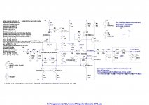
First see the schematics.
I added a ´Dummy-cable´ and a ´Load device´ for more realsistic sims.
I added 4 ´Jumpers´ to quickly change configurations. Simply close or open the jumper after the desired compensation.
Also added the two sources Vi and Li for OL simulation. The AC-value of Vsine must then be set to 0. The OL-amplitude response may be plotted with the term to the lower right for AolB.
For ClosedLoop-sims drag Vi and Li to the ´rest-positions´ at the upper-right and close Jumper4. Change Vsine´s AC-value if desired or drag Vsine´s in-label to Vsquare for rectangle signals (transient Analysis) and plot V(out).
jauu
Calvin
did some sims
First see the schematics.
I added a ´Dummy-cable´ and a ´Load device´ for more realsistic sims.
I added 4 ´Jumpers´ to quickly change configurations. Simply close or open the jumper after the desired compensation.
Also added the two sources Vi and Li for OL simulation. The AC-value of Vsine must then be set to 0. The OL-amplitude response may be plotted with the term to the lower right for AolB.
For ClosedLoop-sims drag Vi and Li to the ´rest-positions´ at the upper-right and close Jumper4. Change Vsine´s AC-value if desired or drag Vsine´s in-label to Vsquare for rectangle signals (transient Analysis) and plot V(out).
jauu
Calvin
Attachments
Hi,
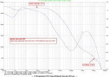
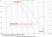
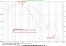
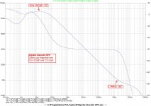
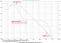
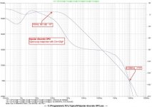
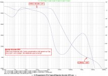
the OpenLoop sims:
the most important point here is, that the phase angle Phi at the frequency where the amplitude drops to 0dB must under all circumstances be greater than -180° (or lower than the abolute value of Phi). If You calculate Phi +180° the result must be >0° (phase reserve). It has been good practise to reach a value of >60° phase reserve.
Miller-compensation of Cm=20pF: Phi@0dB= -173° --> Phase reserve ~7° F0dB=8.59MHz
Miller-compensation of Cm=220pF: Phi@0dB= -117° --> Phase reserve ~63° F0dB=1.45MHz
Miller-compensation of Cm=220pF +C2=22pF: Phi@0dB= -96° --> Phase reserve ~84° F0dB=1.74MHz
RC-compensation of C4=2.2nF, R18=200Ohm: Phi@0dB= -115° --> Phase reserve ~65° F0dB=4.0MHz
RC-compensation of C4=2.2nF, R18=200Ohm+C2=15pF: Phi@0dB= -86° --> Phase reserve ~94° F0dB=7.39MHz
RC-compensation of C4=2.2nF, R18=200Ohm+C2=47pF: Phi@0dB= -118° --> Phase reserve ~62° F0dB=13.1MHz
Its obvious that the RC-compensation allows for higher OL-bandwidth at similar phase reserve.
jauu
Calvin
Attachments
-
 bipolar discrete OP2 - OL w C4 2.2nF R18 200Ohm C2 47pF.jpg357.1 KB · Views: 51
 -
 bipolar discrete OP2 - OL w C4 2.2nF R18 200Ohm C2 15pF.jpg357.4 KB · Views: 56
 -
 bipolar discrete OP2 - OL w C4 2.2nF R18 200Ohm.jpg352.3 KB · Views: 157
 -
 bipolar discrete OP2 - OL w Cm 220pF C2 22pF.jpg350.2 KB · Views: 180
 -
 bipolar discrete OP2 - OL w Cm 220pF.jpg348.8 KB · Views: 193
 -
 bipolar discrete OP2 - OL w Cm 20pF.jpg88.3 KB · Views: 233
Hi,
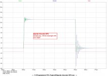
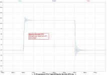
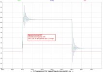
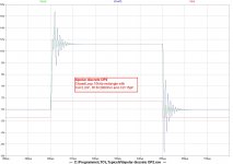
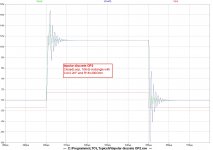
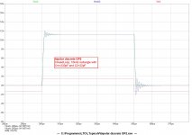
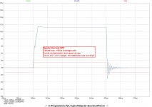
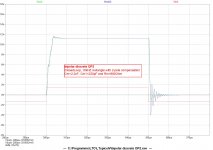
the ClosedLoop sims for a 10kHz rectangle.
As in the OL-sim the 20pF Miller-compensations prooves too low showing some beginning HF-oscillations at the rising edge.
The 220pF Miller and slightly better the 220pF+20pF show just a bit of overshoot, but remain stable.
The RC-compensation also remains stable but shows considerbly more overshoot.
You may try other compensation methods, as the LT.asc is attached.
For example for more OL-gain bandwidth with Miller-comp a 2-pole-compensation might come to mind (2n+220pF+1kOhm).
jauu
Calvin
ps: all diagrams have the same legends to allow for direct comparisons
Attachments
-
 bipolar discrete OP2 - CL w Cm 20pF.jpg200.9 KB · Views: 58
 -
 bipolar discrete OP2 - CL w Cm 220pF.jpg196.4 KB · Views: 52
 -
 bipolar discrete OP2 - CL w C4 2.2nF R18 200Ohm C2 47pF.jpg207.5 KB · Views: 36
 -
 bipolar discrete OP2 - CL w C4 2.2nF R18 200Ohm C2 15pF.jpg212.3 KB · Views: 42
 -
 bipolar discrete OP2 - CL w C4 2.2nF R18 200Ohm.jpg209 KB · Views: 40
 -
 bipolar discrete OP2 - CL w Cm 220pF C2 22pF.jpg199.7 KB · Views: 35
Last edited:
Hi
2-pole compensation (2n2, 220p, 680R) and 2-pole compensation plus speed-Up cap (2n2, 220p, 680R +47p).
The rising response is now cleaner, juts some ringing on falling response.
OL-bandwidth is greater as with Miller.
jauu
Calvin
ps: Its a good thingie to learn from, if he wants to create poweramps later. ;-)
If You question this design, then one could question the sensibilty of high-OL-gain, high-global-feedback designs for a low-closedloop-gain stage anyway.
I certainly would do different also, but that was not the Q at the beginning of the Thread
Attachments
-
 bipolar discrete OP2 - CL w 2-pole 2n2 220p 680R C2 47p.jpg207.8 KB · Views: 39
 -
 bipolar discrete OP2 - CL w 2-pole 2n2 220p 680R.jpg206.1 KB · Views: 54
 -
 bipolar discrete OP2 - OL w 2-pole 2n2 220p 680R C2 47p.jpg361.4 KB · Views: 56
 -
 bipolar discrete OP2 - OL w 2-pole 2n2 220p 680R.jpg358.2 KB · Views: 55
Last edited:
Whoa! That's some incredible work Calvin, I really need to spend some time learning how to use LTSpice the way you do (like a pro). I didn't get a moment to myself to spend on the project this weekend but tonight I (hopefully) with have a spare hour to play with your simulation and learn from it. I'll take some photo's of the oscilloscope output as well to show what the amp was doing.
Exactly! The entire goal for this exercise was to develop an understanding of the 3 stage amplifier topology. It's easier and cheaper to go small scale first as a breadboard can be used along with super cheap transistors, so a single ended class A preamp was the order of the day. The lessons learned from this exercise are going to invaluable when it comes time for me to start developing a discrete power amp.
ps: Its a good thingie to learn from, if he wants to create poweramps later. ;-)
If You question this design, then one could question the sensibilty of high-OL-gain, high-global-feedback designs for a low-closedloop-gain stage anyway.
I certainly would do different also, but that was not the Q at the beginning of the Thread
Exactly! The entire goal for this exercise was to develop an understanding of the 3 stage amplifier topology. It's easier and cheaper to go small scale first as a breadboard can be used along with super cheap transistors, so a single ended class A preamp was the order of the day. The lessons learned from this exercise are going to invaluable when it comes time for me to start developing a discrete power amp.
These designs all seem horrendously complicated. Why try to emulate a power amp design in the first instance.
Yeah, I agree. It would be far easier to just use a 1:4 step up transformer followed by some kind of buffer if he only needs a little bit of gain. If he just needs unity gain then a diamond buffer would be better.
But, if he just wants to learn about power amps then this is one way to do it.
Last edited:
Yeah, I agree. It would be far easier to just use a 1:4 step up transformer followed by some kind of buffer if he only needs a little bit of gain. If he just needs unity gain then a diamond buffer would be better.
But, if he just wants to learn about power amps then this is one way to do it.
Yup, the goal is to learn about the three stage amplifier structure found commonly in power amps. I understand that a simple buffer would suffice for a preamp and could sound better, but that isn't the goal of this exercise.
From doing this I have learned a great deal and it has helped to make clear to me just what else there is to learn about and experiment with.
I'm enjoying every step of this journey and I'm looking forward to the destinations that it will lead to.
I recommend Bob Cordell's book then.
CordellAudio.com - Home
Good luck.
Hi,
sure a good recommendation, as well as Randy Sloane´s book "High Power Audio Amplifier Construction manual". But as I mentioned before both books only bespeak dominant pole compensation and its variant the 2-pole-compensation (at least up to Cordell, third edition). Alternatives are hardly mentioned, let alone that alternatives are discussed in detail. It implies that all amplifiers were created equal.
I regard this as a big malus for books that want to teach amplifier design.
jauu
Calvin
You are mistaken - Cordell's book goes into various other forms of compensation and also covers many additional topics that the other two don't.
It's the Self and Sloane books that limit discussion to dominant and two pole. The Sloane book is more of a practical builder's guide intended for the hobbyist and has minimal theory that seems to be mainly based on Self's work. As such I don't think it adds much value for an EE that already has the Self book.
It's the Self and Sloane books that limit discussion to dominant and two pole. The Sloane book is more of a practical builder's guide intended for the hobbyist and has minimal theory that seems to be mainly based on Self's work. As such I don't think it adds much value for an EE that already has the Self book.
This is a great idea. While I had intended to use smd resistors as I already have some, I was unaware however of matched 8xx series transistors available in a dual package. The BCM8x7 look especially good and are easily sourced so they will definately be used in my final design.
The BC847BS is not "matched" - the two die in the package are separate and could come from anywhere on a wafer or even from two different wafers. They could be at opposite ends of the distribution for their parameters.
Have a look at the DMMT3904 - these are "adjacent die" parts, where the two die were next to one another on the wafer, so are likely to match closely.
Signs of life....
Apologies to those who have helped me so far. I had to put this project to one side for a few weeks. I'm back to work on it again now.
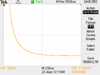
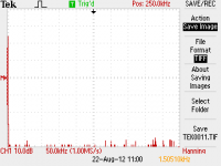
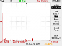
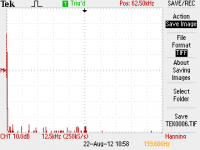
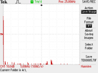
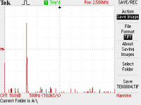
Pics below are:
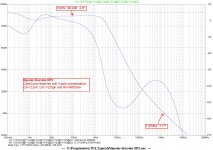
FFT screen captures at frequencies from 1, 10, 20, 50, 100 & 150(kHz)
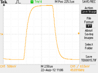
A square wave corner at 10kHz
Square waves 1, 10, 50 (kHz)
It was impossible to tell accurately see let alone measure the harmonics as they all appear to be at or below the noise floor, which was constantly moving about. I guess this isn't necessarily a bad thing.
Apologies to those who have helped me so far. I had to put this project to one side for a few weeks. I'm back to work on it again now.
Pics below are:
FFT screen captures at frequencies from 1, 10, 20, 50, 100 & 150(kHz)
A square wave corner at 10kHz
Square waves 1, 10, 50 (kHz)
It was impossible to tell accurately see let alone measure the harmonics as they all appear to be at or below the noise floor, which was constantly moving about. I guess this isn't necessarily a bad thing.
Attachments
-
 SQR 50kHz.png7.4 KB · Views: 50
 -
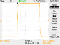 SQR 10kHz.png7.1 KB · Views: 45
 -
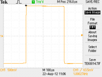 SQR 1kHz.png7.2 KB · Views: 48
 -
 SQR Corner 10kHz.png6.8 KB · Views: 45
 -
 FFT 150kHz.png6.6 KB · Views: 52
 -
 FFT 100kHz.png6.6 KB · Views: 220
 -
 FFT 50kHz.png6.5 KB · Views: 218
 -
 FFT 20kHz.png6.5 KB · Views: 220
 -
 FFT 10kHz.png6.4 KB · Views: 225
 -
 FFT 1kHz.png6.7 KB · Views: 231
Last edited:
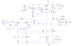
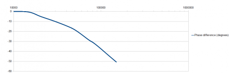
Circuit that was tested and phase
Here is a diagram of the circuit that the above FFT's etc were measured from.
Also attached is the measured phase. From 10kHz - 150kHz
(note: this was done by measuring the time difference between peaks using the o'scope curser and then the data recorded in a spreadsheet. Peak location had to be done by eye and as a result the curve isn't perfect - but it's close enough to see what's going on).
Attachments
Sounds like your having fun.
The phase shift looks a bit excessive over the audio band. I would have to analyse the circuit but you should measure after the input filter (although that won't make a huge difference). Limited slewing of the VAS (C15) might be worth looking at.
The phase shift looks a bit excessive over the audio band. I would have to analyse the circuit but you should measure after the input filter (although that won't make a huge difference). Limited slewing of the VAS (C15) might be worth looking at.
The combination of C4=2n2F and C15=180pF seems like far too much HF local feedback for a stable amplifier.
How low can these values go in simulation before instability becomes obvious? Then you can increase them a little.
C2 seems a little high.
I like the idea of including some cable effects in the sim. Does it make any/much difference when the cable effects are removed/added/increased?
R16 seems too high. Base current of Q8 must be >>> than Q7Ib !!!! Or maybe better to give Q8 it's own source so that big loading effects from Q8Ib don't feedback through to Q5.
Personally, I would replace the current mirror with a pair of resistors and remove the VR to be replaced with 100r 0.1% matched fixed resistors. Then use a trimmer across R5 to balance the LTP.
R12 & R10 can be reduced by a factor of 3 if you adopt the Cherry style of feedback. This maintains the same DC conditions across the LTP and reduces the odd filtering behaviour of the amplifier @ very low LF.
eg, use 6k8 & 15k for the actual feedback. Then add a 30k//~~5uF in series with R10. This gives a DC resistance of 45k on the -IN of the LTP. It gives the noise effect of the 6k8 on that -IN and it removes the hump from the LF roll-off.
The +IN sees ~ 48k so nearly matches the new 45k value and you can trim the 47k to minimise the output offset (the LTP currents are already balanced) due to slight errors in selecting the transistors.
Once you have Q1 Ie = Q2 Ie and the Vbe voltages the same (= zero output offset) you will find that the output offset is very stable with changes in amplifier temperature (thermal coupling of the LTP helps here). This shows in the start up from cold output offset being very similar to the hot operating output offset & the quiescent offset. They all remain very close to 0mVdc. But this only works when Q Ie are equal !!
Last edited:
Hi Andrew, thanks for the incredibly helpful post.
The above pics are from an actual circuit constructed on a bread-board, the RCA cable part labeled on the schematic is just a worst case scenario guesstimate of an actual RCA used in the test. The input components after the RCA are also mounted on the breadboard.
I had never heard of Cherry before so on my lunch break today I searched for articles describing Cherry feedback and I came across this gem: http://www.linearaudio.nl/Miscellaneous/cherry ndfl.pdf
It's one of the best things I've ever read with regards to feedback theory & I'd like to try his method as you've so kindly suggested.
- Status
- This old topic is closed. If you want to reopen this topic, contact a moderator using the "Report Post" button.
- Home
- Source & Line
- Analog Line Level
- Class A preamp: please critique my circuit and give me helpful suggestions.