why do you think i should replace the diode ? is it becasue of voltage drop across it ? also how much am i getting by replaceing the 1uf cap that goes after inductor to ground becasue it s really hard to solder a 1uf 100v cap to a smd solder pads. and lower capacitance input caps should get me lower cutoff frequency right ? while i am at it should i replace the 10uh inductor with 22uh ?and what would that do ?
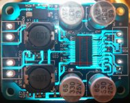
I double checked. The dents are definitely real, looks like a bit of the epoxy package got chipped off between the pins somehow. Not my doing, this board is unmolested (for now). The laser marking is actually off to the side as well. I have 6 other TPA3118 boards, a few varieties from all different sellers. None of those have the dents, but the laser marking is in the same spot for all of them.
Who knows, it wouldn't surprise me if they were all counterfeit chips. They do all work as intended though.
Who knows, it wouldn't surprise me if they were all counterfeit chips. They do all work as intended though.
why do you think i should replace the diode ? is it becasue of voltage drop across it ?
I'm basing it on the assumption that the included diode is cheap (and it pretty much has to be for the boards to sell for $8 shipped internationally). Assuming you are using a high-quality power source, and know you'll never mix up the power polarity, why would you want a cheap diode of unknown quality sitting in your power path?
That said, will it make an audible difference? Try it and see.
")
also how much am i getting by replaceing the 1uf cap that goes after inductor to ground becasue it s really hard to solder a 1uf 100v cap to a smd solder pads.
Hard to say how much you'll get, if anything. From my observation of this thread, few people are modding the Sanwu tpa3118 boards, except perhaps changing the gain setting. In the big tpa3116d2 thread, lots of people (including me!) did all kinds of component changes, with varying degrees of improvements reported. Were those real or imagined improvements? That's a debate, a can of worms I'd rather not open.
and lower capacitance input caps should get me lower cutoff frequency right ?
The tpa3116d2 datasheet has a nice table on page 14 that shows recommended input capacitance versus gain setting:
Code:
GAIN   INPUT IMPEDANCE INPUT CAPACITANCE HIGH-PASS FILTER
20 dB  60 kΩ           1.5 µF            1.8 Hz
26 dB  30 kΩ           3.3 µF            1.6 Hz
32 dB  15 kΩ           5.6 µF            2.3 Hz
36 dB 9 kΩ 10 µF 1.8 Hzwhile i am at it should i replace the 10uh inductor with 22uh ?and what would that do ?
Depends on the impedance of your speakers. The idea is that you are creating a filter to remove the high frequency switching noise introduced by the tpa3118 chip itself. There has been lots of discussion on this topic in the numerous tpa311x threads...
Just made up a foam core prototype for my beach boogie boxes. Internal dims 12x12x6.25. The 6.25 is 8inch coax face to face dimensions when magnets are together. Might glue a spacer in-between mags to get some more width? Making these out of styrofoam I'm afraid they will hop all over the boat/beach? Was dreaming about great tunes at the island and it came to me.....somehow add a microphone so people can karaoke??? Is it possible with the cheap Chinese amps to make a portable batt powered karaoke player??? Think drunk bikini girls singing ???lol
So I hooked them all up and sound pretty dam good. Question: I currently have all 4 drivers running off one amp with 19v 2.53amp Samsung brick PSU. Is this correct? When I say all 4 drivers I am referring to two 8inch 4 ohm woofers and two 8ohm tweeters all off one 3118. Even though they are coaxial speakers the leads are separate. I know that in boominator the drivers in one box are running the same channel. Or should I run one amp to one tweet/woofer, and one for the other but run one channel say right side from input to both amps? So a total of 4 amps, two for each side/channel?
Thanks mat garman for the reply it looks like the best thing to do is
1). add the heat sink from underneath
2). Replace 10uh inductors for 22uh because I use 8ohm speaker
3).add some bulk capacitors on the power input
4).lowering the gain to 26 or 30 db maybe 26 is too low ?
5).adding an on off switch
I will post a picture of my portable speaker prototype later today for all of you to see maybe give me some advice.i plan to build another one of those and make a diy video tutorial for youtube


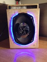
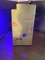
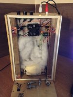
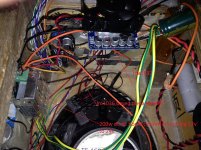
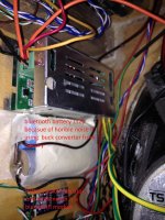
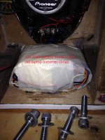
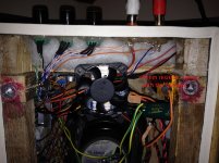
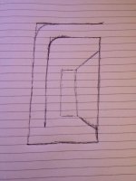
so this is my portable speaker. i know it s very ghetto but it works . i have been playing music on it for almost a year now. but now i want to build the mk2 version of it and i want to improve the sound quality as much as posible and do a diy video tutorial for youtube.so if anyboda has any ideas on how to improve it please contribute. the first thing i want to improve is to add a longer L port (drawing below ) the second thing is the amplifier mods that i mentoined in earlier post , and the third thing that i want to do is to isolate the amplifier from preamlifier and bluetooth module from the amp. i already tried doing that with cheap ebay groud loop isolator but i only got more noise in the amplifier maybe it s becasue they are not shielded with metal i could try wraping them in some aluminium foil would that hep ? and thats about it from me if you have any other suggestions please post
. i have been playing music on it for almost a year now. but now i want to build the mk2 version of it and i want to improve the sound quality as much as posible and do a diy video tutorial for youtube.so if anyboda has any ideas on how to improve it please contribute. the first thing i want to improve is to add a longer L port (drawing below ) the second thing is the amplifier mods that i mentoined in earlier post , and the third thing that i want to do is to isolate the amplifier from preamlifier and bluetooth module from the amp. i already tried doing that with cheap ebay groud loop isolator but i only got more noise in the amplifier maybe it s becasue they are not shielded with metal i could try wraping them in some aluminium foil would that hep ? and thats about it from me if you have any other suggestions please postAttachments

So I hooked them all up and sound pretty dam good. Question: I currently have all 4 drivers running off one amp with 19v 2.53amp Samsung brick PSU. Is this correct? When I say all 4 drivers I am referring to two 8inch 4 ohm woofers and two 8ohm tweeters all off one 3118. Even though they are coaxial speakers the leads are separate. I know that in boominator the drivers in one box are running the same channel. Or should I run one amp to one tweet/woofer, and one for the other but run one channel say right side from input to both amps? So a total of 4 amps, two for each side/channel?
Speakers are complex loads so this isn't necessarily exactly right, but
1/((1/8)+(1/8)+(1/4)+(1/4)) = 1.33333 ohms. Probably a little bit too low, datasheet specs a minimum impedance of 2 ohm in PBTL.
I don't think putting drivers in series is advised, so I would probably use two amps and just feed in one signal to both.
You are correct that 1.6 ohm is the listed minimum, my mistake. I still don't think I would want to run it at 1.333 ohm all the time though. Even more so when I consider that it will be inside of an enclosure, reducing heat dissipation. Better to spread the heat around IMO.
Also, since (I think) the boards are in hand already, unless they are needed or wanted for another project, no reason not to.
Also, since (I think) the boards are in hand already, unless they are needed or wanted for another project, no reason not to.
a commercial tpa3118...good to see a big name using it
Teac AI-101DA: a neat little amplifier with a lovely DAC!
Teac AI-101DA: a neat little amplifier with a lovely DAC!
I am currently running this way and switched back to the 12V 5Ah batt and it gets pretty loud. So Jensen is right, I have a total of 6 of these 3118's so I should use 4 amps total? At very loud volume the backside of chip is just a little above ambient, hardly detectable? Why does it play louder on 12v batt than it does on 19V PSU brick? Thanks all, I am excited about this build. It sounds very good in foam board mock-up with double thickness. Can't wait to hear it out of some thick foam! Split the input into left and right, then split each side into two amps, each driving a 4ohm 8" and an 8ohm tweeter.
Further discussion about the load the amp sees, I haven't added any crossover components to the woofers yet. What would happen if I added an inductor of .33-1.0 to the woofer? Either parralel or series? I didn't add it because the cabinet is flimsy and prob has a large amount of box resonance. Would the inductor add more resistance or less?
Also, about loudness: I think it plays pretty loud on the 12v batt, probably loud enough? This is with a cell phone or tablet as Input but wired. What is the Bluetooth receiver going to do, add gain or take it away? Sorry so many questions! I. Love that teac integrated ampdac. How much is 350 eus in USA dollars?
- Home
- Amplifiers
- Class D
- Cheap TPA3118D2 boards, modding them and everything that comes with it