Try to design a better TPA3118 board that also measures and sounds better and sell it to us for 6 Euro 
Regarding the protection diode in the + line: seemed superfluous to me too. However, I sold some of my older class D modules and then got answers why some of them did not work. Turned out that the owner had connected them with reversed polarity. Not all souls are skilled with electronics. Low prices of China gear make that unskilled people also buy this stuff. I guess the sellers/factories were fed up with complaints that their stuff broke down at the customers. Apparantly many people just connect the red and black wire randomly and then switch the device on. If it does not work then they reverse connect the red and black wire and try again. Also connection of speaker outputs is done randomly.....if there is sound it works...
Regarding the protection diode in the + line: seemed superfluous to me too. However, I sold some of my older class D modules and then got answers why some of them did not work. Turned out that the owner had connected them with reversed polarity. Not all souls are skilled with electronics. Low prices of China gear make that unskilled people also buy this stuff. I guess the sellers/factories were fed up with complaints that their stuff broke down at the customers. Apparantly many people just connect the red and black wire randomly and then switch the device on. If it does not work then they reverse connect the red and black wire and try again. Also connection of speaker outputs is done randomly.....if there is sound it works...
Last edited:
So there might be no damage at all and the pop pop pop here was just overvoltage protection tripping ??? But then why does it keep tripping when chip restarts ? Does the diode cause this ? If overvoltage the ceramics and electrolytics on pvcc aren't likely damaged, their surge rating is much higher than tpachip ?
When you say the mute is wired up, what do you mean exactly? It looks like they have a 100k pull down on the mute pin, and the adjacent pin on the jumper is connected to GVDD with a 10kR in series. Should NOT be muted by default, and I wouldn't advise using that jumper to mute it!
That said, whatever it is you did, may as well try it on the others to see if they can be revived. If it's already broken, what is there to lose?
Here is a photo with much better traces shown. Using my signature method for reverse engineering PCBs, a really bright flashlight, enjoy
EDIT: For the picture worth noting, the only thing on the back side is ground plane, so all vias are to ground.
Well, I simply soldered a lead wire into or onto both solder points labeled mute. Then attached an on/off switch to the leads. The red LED lights on the board always stay lit and the on position on the switch is actually off on the amp. Great way to see the traces on these boards. I will wire up the broke boards after my morn coffee. I wonder how much power is being used when the mute is on and the board is not powering the speakers? They sure are bright now.
@xrk,
for pure boost, you may go for those:
600W DC DC Boost module power constant voltage 9 60V turn 12 80V 48V 72V-in Inverters & Converters from Electrical Equipment & Supplies on Aliexpress.com | Alibaba Group
(Still 10A input current limit)
Wow, so many posts in a few days!
Hey Doc,
I have placed this item on my shopping list. Have you used this booster and have any opinions? Does it look worthwhile to try? Thanks!
EDIT: There is also the super duper "1200W" boost only, which will do 20A
1200W 20A DC Converter Boost car Power Supply Module 8-60V Step-up 12v-83V 24v
@ Jensen,
Any experience with this one? Does it look like it can handle > 1 KW? I am currently looking for a booster converter. Thanks!
The mute has fixed the popping but I think it has increased the shoutiness, or reduced the surupy sweetness that I heard before hooking up the mute? Could just be me though but would coincide with my initial response of louder when first hooked up? Louder in the mid to upper range? Just my impressions. It really is not a big difference from 3116 I have?
@ Jensen,
Any experience with this one? Does it look like it can handle > 1 KW? I am currently looking for a booster converter. Thanks!
I have not used that exact model, but I have used this one
1200W 20A CC CV Boost Converter DC 8V 60V to 12V 80V Volt Step Up Power Module | eBay
What are your input and output requirements?
Boosters are always going to be input limited. These "1200W" will technically do 1200W, if you run at the maximum input specs (60V at 20A).
Otherwise, take your input voltage, multiply by 16A to get your max output power. I assume 80% load here as I wouldn't want to run at 100% all the time.
There will also be some efficiency losses, a safe bet would be to assume 85% eff. Will likely be better, but I prefer to be conservative in my estimates.
Thank you for the reply. Actually I am even more conservative and would assume a 80% efficiency max. I will be real happy if I can get a steady 3-400 W.
Try to design a better TPA3118 board that also measures and sounds better and sell it to us for 6 Euro
I can't, but if you want to test/measure a 3132 board for yourself, let me know.
Wow, so many posts in a few days!
Hey Doc,
I have placed this item on my shopping list. Have you used this booster and have any opinions? Does it look worthwhile to try? Thanks!
They're similar to the small 150W modules, same IC but beafier cooling, switch and coil. As Jensen said, the limiting factor is mainly the switching current, so max power here is also Vin*Imax.
The next limiting factor is your source impedance. So I.e. pulling some 20A from an SLA with 110mR is problematic, as the voltage already drops by 2.2V. If you're operating the converter at the lower limit this can be a problem. So it's a good idea to beef up capacitance. This will mostly/only work for mid-frequencies, not at the low end.
Thank you for the reply. Actually I am even more conservative and would assume a 80% efficiency max. I will be real happy if I can get a steady 3-400 W.
As said right before, source impedance (battery) can be a limiting factor.
Last edited:
Thank you for the reply. Actually I am even more conservative and would assume a 80% efficiency max. I will be real happy if I can get a steady 3-400 W.
If you have 24V or higher input 300W - 400W continuous output should be reasonable. You may want to add a fan to the heatsink to be safe and extend the lifespan.
The mute has fixed the popping but I think it has increased the shoutiness, or reduced the surupy sweetness that I heard before hooking up the mute? Could just be me though but would coincide with my initial response of louder when first hooked up? Louder in the mid to upper range? Just my impressions. It really is not a big difference from 3116 I have?
Do you notice any visible burning of the small components near the output? How about anything near R26 or R30?
Last edited:
I just kind of assembled my new amp It is a double cheap chineese, modded to 20db gain. So far I can only say it is a little bit better than substantially modded blue/black 3116. Bass is definitely more present.
This is an enclosure I have printed. It houses theese two tiny amps and a Meanwell rs7524. Now that I know it works, time for cover and knob printing

It is a double cheap chineese, modded to 20db gain. So far I can only say it is a little bit better than substantially modded blue/black 3116. Bass is definitely more present. This is an enclosure I have printed. It houses theese two tiny amps and a Meanwell rs7524. Now that I know it works, time for cover and knob printing
Last edited:
Connecting to a battery gives multiple voltage and current spikes, the electrolytics will dampen those. If the battery is 20cm from ampboard the 4 electrolytics will dampen the spikes. Earlier I said I thought the surge rating of ceramics was high enough, but voltage surge rating ceramics is at max 50mA current and the frequency of the spikes favour the ceramics.
Connecting to a battery gives multiple voltage and current spikes, the electrolytics will dampen those.
What kind of battery?
Over on the Soekris dam1021 DAC thread, someone mentioned the lifepo4 26650 cells, specifically the ones made by a123. They have crazy low resistance and similarly high current capabilities. Kinda pricey when you buy enough to get the voltage up, that's what's kept me from trying. But they certainly look interesting.
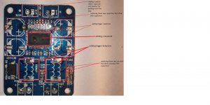
ok so from reading this thread i came to a conclusin to make these changes to my tpa3118 board
i plan to use this amp for my portable speaker with a 4 ohm car speaker and a 4 ohm resistor in series with it, batteries from old laptops , dc-dc boost converter , lm1036 pre-amp.
please tell me your thoughts on these mods as i am a beginner in electronics.
and also i do not quite understand how to get rid of pop noise what values of capacitors and resistor to use ? please help
Attachments
The filmcapacitors for input are only a little bigger than the ampboard, each, leadspacing 52.5mm. Free shipping if you buy just one from Digikey, $57 discount if you buy 10 But the Jensen inputtransformer cost half, because you need two capacitors for input
You could use them for electrolytic position too, but slowly the ampboard will be getting expensive
But the Jensen inputtransformer cost half, because you need two capacitors for input You could use them for electrolytic position too, but slowly the ampboard will be getting expensive
ok so from reading this thread i came to a conclusin to make these changes to my tpa3118 board
i plan to use this amp for my portable speaker with a 4 ohm car speaker and a 4 ohm resistor in series with it, batteries from old laptops , dc-dc boost converter , lm1036 pre-amp.
please tell me your thoughts on these mods as i am a beginner in electronics.
Looks like the "classic" YJ Blue/Black mods applied to this board.
I'd say most probably can't hurt. Based entirely on what I've read in this thread, these boards don't sound terribly robust, I'd be worried that the PCB might not be able to tolerate all the soldering.
I don't think adding a heatsink to the top will do anything useful, as the tpa3118 has its thermal interface on the bottom of the IC. The intent is that the heatsinking is via the PCB's ground plane. If you want to do better thermal management, do like Xrk did earlier in this thread and use thermal adhesive to glue a big heatsink to the bottom of the board. You could also do like the Gmarsh Wiener board and use a thermal pad to bridge the PCB to your chassis (assuming the chassis is metal).
Since you're doing all that modding, while you're at it, you might as well remove what I assume is a power polarity protection diode and replace it with a wire jumper... assuming you can trust yourself never to mess up the power supply polarity.
and also i do not quite understand how to get rid of pop noise what values of capacitors and resistor to use ? please help
I haven't worked with this board personally, but all the other tpa311x boards I worked with suffered power on and/or off popping, except the following:
- Gmarsh Wiener board has a micro-controller that smartly invokes the chip's mute circuit to eliminate power on/off pop.
- When I've used input transformers instead of input capacitors for DC-blocking, the power on/off pop was eliminated.
- The easiest solution is to wire a switch to the mute pin. Then the power-on process becomes: close the mute switch, apply power, open mute switch, enjoy music. Do the exact opposite for power-off.
If you search the huge tpa3116d2 thread, there are a few references to the "Giancarlo" circuit which IIRC eliminates power-on or power-off pop, but not both.
- Home
- Amplifiers
- Class D
- Cheap TPA3118D2 boards, modding them and everything that comes with it