I was going to say the same thing. Surprised he hasn't already - but then why when xrk can get you high res photos of the layout.")
That was for the BT 3118 board, thanks again.
How many volts does a preamp need to clip a PBTL 20dB gain amp? Pro audio levels are 3.4v p-P?
Depends on the supply voltage. The inputs are limited to 6.3V per pin and are biased at ~3V. With 24V supply voltage and a little margin i'd say 4.4Vpp or 1.555Vrms.
On the Vifa TC9FD's i have a turn on thump, too.
But the easily accessable MUTE is absolutely quite when used as on/off switch.
The thump on mine is pretty loud. Did you incorporate an actual on/off switch?
That was for the BT 3118 board, thanks again.
Depends on the supply voltage. The inputs are limited to 6.3V per pin and are biased at ~3V. With 24V supply voltage and a little margin i'd say 4.4Vpp or 1.555Vrms.
20dB is too low of a gain then. I will have to dig up some SMT resistors or scrap them off some junked pcb's to get 26dB.
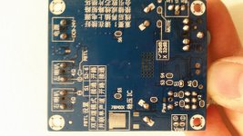
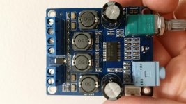
As promised from the 3116 thread, here are photos of the new version of the "SMAKN" board from amazon. Also available from a few sellers on ebay, but not having to wait is nice.
http://www.amazon.com/gp/aw/d/B015F...i=AC_SX236_SY340_FMwebp_QL65&keywords=tpa3118
I would say this version sounds at least as good as the old layout to my ears (I have both versions, if anyone wants better pictures than what is on Amazon of the old version). They did move away from GSK caps to literally no-name, not that GSK is particularly great anyway.
EDIT: FAIL! Way to not attach pictures to the post which its sole purpose was for pictures.
Attachments
Last edited:
I think having a simple SPST toggle switch for mute or un-mute is the simplest solution to the thump problem is it bothers you.
In an earlier post I showed what can be done to avoid pop (what I did on mine to solve this issue) - here.
It will require some careful soldering, though...
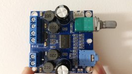
It's certainly different than the SMAKN 3118 I had gotten previously, which was disappointing at first, but then I asked them about it, got a full refund, and a second matching board of the new layout for free. Here is the old board I had gotten before. Similar, but slightly different. The older board was actually smaller which was nice, but the new one looks to have a bit nicer signal path.
Attachments
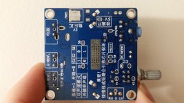
OK newer adds outputsnubber and adds decoupling for PSU pins, for both the four S5 S6 pads are made for bootstrap snubbers, not really, designer has PBTL in mind with them, but easy snubber location too even for two when in PBTL.
edit:for both bottom pad 3118 doesn't seem soldered
edit:for both bottom pad 3118 doesn't seem soldered
Cool, so it probably isn't entirely my imagination thinking that the newer one sounds a bit better.
On the new one the bottom pad is definitely soldered, though lightly, you can see the solder in the vias. On the original one, it is either not soldered, or extremely light. Thankfully they didn't put solder mask on that one, so I can fix it.
I would love to know what some of the "secret" pads on these boards do too if anyone can read Chinese, or just knows based on the chip pinout. Specifically, the "AG" pad. Auto gain?
Last edited:
Could be, but when I said pad, what I meant was 2 pads, because it is really a jumper link (open by default).
You can see it near the volume pot on the back of the new SMAKN board I posted. On the old SMAKN board I believe the same jumper is labeled "PC MODE", but I could be wrong about those jumpers having the same function between boards.
You can see it near the volume pot on the back of the new SMAKN board I posted. On the old SMAKN board I believe the same jumper is labeled "PC MODE", but I could be wrong about those jumpers having the same function between boards.
Thanks for the help on the hiss question.
Found some data on it:
TPA3118D2 | Mid/High-Power Class D Amplifiers | Audio | Online datasheetCode:gain R1 R2 inR cap 20db 5k6 open 60k 1u5 26db 20k 100k 30k 3u3 32db 39k 100k 15k 5u6 36db 47k 75k 9k 10u
If I used a 30k and 100k, would it be close enough to get 26dB? I know that it just needs to get in the right range for the start up ADC to read the correct voltage to set the gain.
I managed to find these values from an old microwave distribution amplifier/switch for Dish Network.
In an earlier post I showed what can be done to avoid pop (what I did on mine to solve this issue) - here.
It will require some careful soldering, though...
Thanks for reminding us. How did you do the jumper? I have a 1.63v SMT Zener diode, will that work?
Photos of your implementation?
Would guess V1+V2 bypasses the pot, but AG, hmm.. from the (blurry) picture it looks like the AG pad is connected with a thin trace by default.
Considering those were taken with a smartphone, one handed, with no stabilization, they're not so bad. But point taken. Haha. Examining the circuit more closely, it would appear AG jumps the common side of the volume pot to input signal ground.
EDIT: xrk where in VA are you? I'm right over the river in MD and could probably get you basically any value smd resistor you could need if those don't work.
Last edited:
If I used a 30k and 100k, would it be close enough to get 26dB? I know that it just needs to get in the right range for the start up ADC to read the correct voltage to set the gain.
I managed to find these values from an old microwave distribution amplifier/switch for Dish Network.
The layout is such that even 1/4w ordinary through hole resistors would work fine so long as you can find the flux, preferably gel flux.
I have not received my board yet. But, if it comes in at 36db and hissing, I will be changing some resistors. If it were convenient, I have some axial 1/8W resistors handy. Actually, I don't have any SMD resistors--I blame the cats.
- Home
- Amplifiers
- Class D
- Cheap TPA3118D2 boards, modding them and everything that comes with it