Thanks for your suggestions, and I would perhaps have implemented them, if you had shown more details and a schematic of what changes you suggested.
I think the design I have now achieves its goals, and kindly suggest that you start your own thread for further discussions of your ideas on improving the circuit.
C'mon shaq888, the ball is in your court - please help out with schematics or please start a new thread.
")
That's funny and sad simultaneously to see all those efforts are wasted by a few basic mistakes. Too bad you never get to making any better measurements that you did. It could help you to avoid making those.
Hello shaq,
could you to point on the schematic, of the improvements you are talking? or the basic mistakes xrk971 is making?
a picture is worth a thousand words for me.
regards
prasi
Hello shaq,
could you to point on the schematic, of the improvements you are talking? or the basic mistakes xrk971 is making?
a picture is worth a thousand words for me.
regards
prasi
I'd like to see a schematic as well Shaq. Afterall, isn't the DIY spirit about helping each other out as a team to better our designs?
That's funny and sad simultaneously to see all those efforts are wasted by a few basic mistakes. Too bad you never get to making any better measurements that you did. It could help you to avoid making those.
This is DIYAUDIO ! I also would like to see what you have to offer.
you talk the talk now walk the walk
Hey Shaq888,
Why don't you get out of your armchair, put your phone down (according to your own statement that is how you are posting) and just post a bloody schematic and enlighten us all.
This isn't sarcasm its simply asking you to impart you logic via a picture.
Seriously, this is just a hobby. Keep it fun, be helpful and enjoy. If someone doesn't take your help, then that's their loss.
Cheers
Quistion is could there be a morale in place here that needs X camp look a bit inside too ? for a long time X have dribled around into diverse amp and speaker forums and subjective declared any sign of cold or clinic sound to be coursed by amps having negative feedback or multiple chips or too many active switching devices or wrong stability compensation, maybe these claims hurt Shag888 especially because design in this thread use topology that is his home and he can't bear that just because things goes fast plus PCB is stamped with xrk971/JPS64 logo and prasied by AKSA it would probably later on subjective side be declared one of the best chip amps.
When X request design help in spirit of diy from other designers i can't stop thinking about it doesn't help much that he started his own audio company.
Suggest be bit more open minded and stop this banning of topology or feature war based on personal subjective conclusions that sometimes can be way off for many reasons, also it could maybe help publish all or more objective measurements not only the shining one about distortion scheme.
When all comes to all what we hear in the end is about a band limited 20Hz to 20kHz audio band so think one shall be carefull into subjective conlusions of upstream devices and personal have more than once experienced the most ugly system or topology perform subjective as a million when executed by the right hands.
Last edited:
I'd like to see a schematic as well Shaq. Afterall, isn't the DIY spirit about helping each other out as a team to better our designs?
He already gave advice that was ignored for the most part.
Also, I thought this was diyAudio, not help me design something I can sell on Etsy audio.
Hi Byrtt,
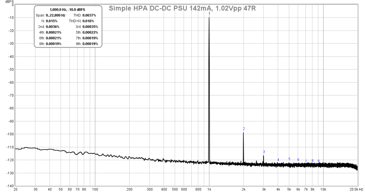
Thanks for your input. I think you know that I like simple SE Class A designs, preferably zero feedback or low feedback. As you can see, with this thread, was my attempt to be open minded about the potential power of complex chip amps with negative feedback. So I am indeed looking at other topologies, with what may potentially be 9 opamps with perhaps 20 actives each. I don’t think I ever went about “banning” any topology and I post all my data, even when they don’t perform like I hoped. The measurement of the FFT for the double buffer 1688 for example, shows it’s clearly off from the model - which Shaq pointed out was flawed. I accept that and will move on to try other things. But having no schematic makes it hard for me, personally. Having said that, I think a HPA that has 0.003%THD with a dominant second harmonic and less third harmonic and nothing else - is perfectly great sounding. I am certainly open to all topologies having built about 3 dozen amps including many Class AB and Class A design on DIYA. They all have merit and can sound good. It comes to personal preference for a signature of one amp vs another.
Thanks for your input. I think you know that I like simple SE Class A designs, preferably zero feedback or low feedback. As you can see, with this thread, was my attempt to be open minded about the potential power of complex chip amps with negative feedback. So I am indeed looking at other topologies, with what may potentially be 9 opamps with perhaps 20 actives each. I don’t think I ever went about “banning” any topology and I post all my data, even when they don’t perform like I hoped. The measurement of the FFT for the double buffer 1688 for example, shows it’s clearly off from the model - which Shaq pointed out was flawed. I accept that and will move on to try other things. But having no schematic makes it hard for me, personally. Having said that, I think a HPA that has 0.003%THD with a dominant second harmonic and less third harmonic and nothing else - is perfectly great sounding. I am certainly open to all topologies having built about 3 dozen amps including many Class AB and Class A design on DIYA. They all have merit and can sound good. It comes to personal preference for a signature of one amp vs another.
Last edited:
He already gave advice that was ignored for the most part.
Also, I thought this was diyAudio, not help me design something I can sell on Etsy audio.
Not ignored - as I asked for more details on implementation but was not given the needed schematic.
Just to clarify, the amps designed on DIYA were sold as group buys, and then moved to Etsy to make the logistics and tracking easier for the random post-GB orders that come through. The pricing is the same - it just helps me keep organized and assists me to get the board out to people who want it faster and more hassle free. There is one amp I have that was designed outside of DIYA and never shared here - so not the same.
Last edited:
He already gave advice that was ignored for the most part.
Also, I thought this was diyAudio, not help me design something I can sell on Etsy audio.
A lot of people here have their own company or shop ... mr. Pass himself for example, but i don't think it has anything to do with this forum and their contributions, or we can just go ahead and ban anybody that is a pro and making money of this !
A lot of people here have their own company or shop ... mr. Pass himself for example, but i don't think it has anything to do with this forum and their contributions, or we can just go ahead and ban anybody that is a pro and making money of this !
Xrk clarified for me.
I am not against that, but it looked like Shaq was being asked to spoon-feed information to be directly used in a commercial product. Which isn't that cool, IMO.
Xrk clarified for me.
I am not against that, but it looked like Shaq was being asked to spoon-feed information to be directly used in a commercial product. Which isn't that cool, IMO.
we are getting off topic here, but i understand your frustration, some people here are getting advantage of what s going on to the point that I remember while back Carlos was complaining that he found his designs on ebay! but that doesn't stop people to help each other and bashing someone's idea is just not what this is about
I dont feel bad if xrk971 take some low price money for his stuff.
He will not be rich by this.
If he gets a little pay for his nice work, I think it is only fair.
He just cant give it away for free, you know.
This thread should be getting back on track.
And discuss the design and the technical stuff of this good amplifier.
He will not be rich by this.
If he gets a little pay for his nice work, I think it is only fair.
He just cant give it away for free, you know.
This thread should be getting back on track.
And discuss the design and the technical stuff of this good amplifier.
That’s quite impressive that you can spot mistakes on a new OPA1622 buffer amp design and layout without seeing the schematic as that was not posted. Thanks for your suggestions, and I would perhaps have implemented them, if you had shown more details and a schematic of what changes you suggested.
I think the design I have now achieves its goals, and kindly suggest that you start your own thread for further discussions of your ideas on improving the circuit.
Well, there are just certain things in pcb layout that you don't do no matter what the schematic is and what an opamp have been used. I mean you did quite a few of them.
I described my suggestions, including some tips on layout quite clearly earlier, some of them even several times. Seems like everyone got what I was talking about except you.
Beside that it was mentioned before, drawing schematic for someone on diy forum who is obviously here to promote their commercial products... sorry, it is just one of those things that I don't do.
Last edited:
Well, there are just certain things in pcb layout that you don't do no matter what the schematic is and what an opamp have been used. I mean you did quite a few of them.
I described my suggestions, including some tips on layout quite clearly earlier, some of them even several times. Seems like everyone got what I was talking about except you.
Beside that it was mentioned before, drawing schematic for someone on diy forum who is obviously here to promote their commercial products... sorry, it is just one of those things that I don't do.
It’s easy to criticize and not back anything up with specifics. Just like it’s easy to “help” and provide “tips” and give no specifics. I can see how important good layout is, like the recent amp you just made nice measurements of -155dB 2kHz distortion peak using an SR1 analyzer (nice piece of gear Btw). Your plots always seem to have the noise floor at -160dB and nothing higher than -120dB is displayed. Most of the time, when FFT data is presented, the full scale of the peak signal is also shown (circa 0dB) for comparison. Or maybe your data has a range of only 40dB?
Regarding all your fears of commercialism on my part. I already explained that the amps developed on DIYA are provided in GB’s and I use the shop to simplify the logistics of post-GB board sales at the same price.
Last edited:
I was very specific oh the beginning. Now I just see no point.
So, you think whereever fft shows that wiggly line at the bottom that is SNR if the carrier at 0ish dB?
Still gave no desire to draw any schematic for you. If you are smart enough to push commercial projects here you should be able to draw schematic yousrself.
So, you think whereever fft shows that wiggly line at the bottom that is SNR if the carrier at 0ish dB?
Still gave no desire to draw any schematic for you. If you are smart enough to push commercial projects here you should be able to draw schematic yousrself.
Last edited:
I said nothing of SNR - just that it’s hard to tell true range of measurement. If you look at any FFT plot published by TI, for example here is OPA1622 for a certain case, the vertical axis always goes at least up to 0dB for reference.
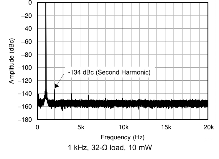
Or when I present the FFT data, I show the peak value of the excitation frequency of 1kHz.
Clipping the plot off at -120dB makes it unclear what the peak of the 1kHz excitation value is - as the distortion peaks are relative to it.
What we get with your plot is a zoomed in view of the floor, but where does the peak lie? It matters because what gain you use changes that. Use 20dB major divisions with 0dB in sight rather than 2.5dB divisions.

I’m not going to ask for any schematic - that’s about as dead as a horse will ever get.
Or when I present the FFT data, I show the peak value of the excitation frequency of 1kHz.
Clipping the plot off at -120dB makes it unclear what the peak of the 1kHz excitation value is - as the distortion peaks are relative to it.
What we get with your plot is a zoomed in view of the floor, but where does the peak lie? It matters because what gain you use changes that. Use 20dB major divisions with 0dB in sight rather than 2.5dB divisions.
I’m not going to ask for any schematic - that’s about as dead as a horse will ever get.
Attachments
Last edited:

- Status
- This old topic is closed. If you want to reopen this topic, contact a moderator using the "Report Post" button.
- Home
- Amplifiers
- Headphone Systems
- Cheap as Chips OPA1688 Low-THD Muscle Amp