I didn't want to bring a post this old, .. but what do you think about the performance of the PE 299-609 buyout drivers vs the GRS drivers in a slot loaded open baffle of my own creation . I'm not worried about crossovers ( I can go active) . On paper, it's a bit of a wash .. the GRS speaker has a bit beefier magnet but the buyout driver has somewhat lower Fs + higher efficiency (but higher impedance / lower sensitivity) in an 8 driver array .Edit April 28, 2022 - XSD Speaker is here: 8x 6.5in woofers, 5.25in neodymium motor paper midrange, 3in planar dipole tweeter. 91.5dB sensitive st 2.83v, -3dB at 43Hz and -6dB at 37Hz.
View attachment 1049129
View attachment 1049132
Cheap and fast FAST bi-amped OB
Edit: latest results with 6 driver slot loaded woofer - see post 67.
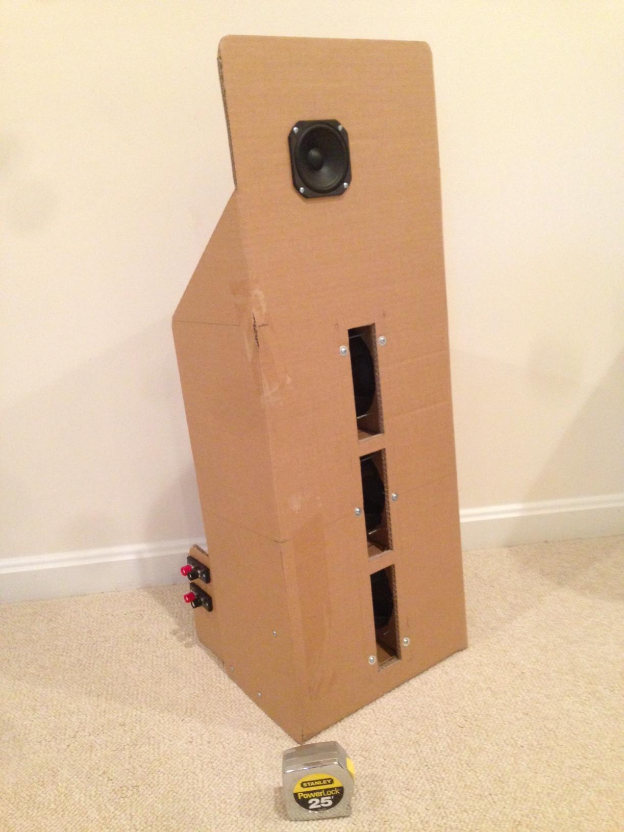
Having a bunch of Vifa TC9FD's in hand from when they had the sale for $10 ea, and a few more of the PE 6.5 in polycone woofers (part 299-609) for $4.88 ea lying around... I thought I should try a FAST open baffle, that can be made in less than 1 hr. Having measured both of these drivers in a 24 in x 36 in cardboard baffle before, I knew they had very flat responses, and being high Qts drivers would lend themselves to an OB. I also happen to now have a miniDSP to handle the XO and EQ duties, and I planned to bi-amp them. I am convinced that messing with huge inductors, and huge poly film caps for a passive XO will end up costing just as much as a minDSP and a pair of class D amps.
I happened to have some double-wall corrugated cardboard on hand that measured 12 in x 18 in. Guess what, that is now my OB baffle size. I had some more cardboard that I used to make some wings and the stand for the baffles. These ended up as 8 in deep at the base and going to 3 in deep 15 in up. I gave a tilt backwards to add stability and aim it up. The 6.5 in woofer is mounted 5 in from the bottom at the middle. The Vifa fullrange is mounted 5 in from the top and 4.5 in from one of the edges. I made it asymmetric to reduce diffraction. I added a 2.75 in deep cross brace on the back that will also come in handy for the binding posts. Everything was cut and tacked with a few points of hot melt and glued with Titebond at all seams. Cutting and gluing took 30 minutes. Screwing the drivers in and adding crimped connectors took another 15 minutes. Waiting for the glue to dry took 3 hours.
I tried running both drivers in parallel and full range to see what it sounded like - just a terrible mess. I then connected the drivers in a bi-amp configuration and driven by the miniDSP with a 24 dB/oct XO at 300 Hz.
The miniDSP setup took 15 minutes. Taking a measurement with the mic showed that it was pretty good but had a few minor dips and peaks that were easily EQ'd out. The bass extension is natural - no EQ'ing needed - it really does go to 50 Hz with the modest wings.
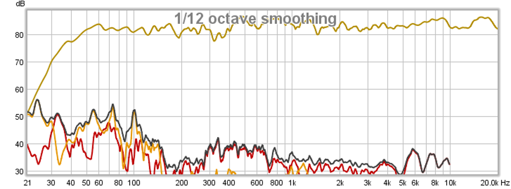
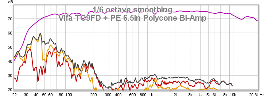
Here is the frequency response and distortion - nice flat response and low THD from the Vifa above 300 Hz. Below 300 Hz, the 6.5 in driver's cone excursion is starting to get taxed and hence THD goes up. Adding more woofers will reduce excursion and reduce THD. If I had more drivers, I would have used two in series for 8 ohms.
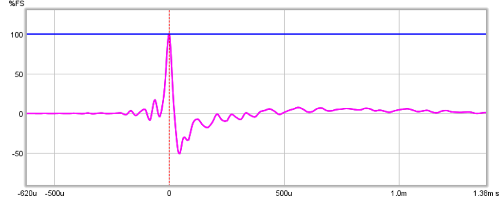
Here is the impulse response - doesn't get much better than this.
So how does it sound? Fantastic! It has some very nice clean dynamics capable of reproducing fast transients and percussion. It doesn't go very loud as the Vifa is nominally 85 dB at 2.83V but perfect for near field or low level listening. The sound stage is what is perhaps the best part - very wide and I can close my eyes and pinpoint the location of the singer, the instruments, and where they are positioned on the stage.
Anyhow, not including glue drying time, all this was done in about 90 minutes. Cost is $20 per speaker including binding posts. Now that is a cheap and fast FAST that sounds great and measures well.
Thanks
Hey, Ho!
Why is this thread so deep now?
We need to wake it up a bit!
I am afraid I will have to forget about doing OB, the sound I love, but now my living room is down to 12' x 12' (4.6m x 4.6m).
Shown in pic with sofas and TV placement.
That is not much space for OB to breathe.
I just saw these... the Piega Master Line Source 3. They say it's OB (mid and highs) with bass using woofers and passive radiators, and it can be placed like regular speakers as they use some kind of acoustic lens in the back. The lens is said to diffuse the sound like OB, but not induce problems like OB speakers placed too close to a wall. Yet, in their intro video, they are placed pretty much away from the walls!
Hmmm... Anyone has heard anything like that?
https://www.av-connection.com/?PGr=12317
No I haven’t seen those before. Cool looking.
You could do the dual TC9FD in narrow OB above a skinny bass reflex box underneath in FAST in your sleep and it would look much like the above.")
Or dual GRS PT6825-8 planars above quad 6.5in Peerless woofers with reflex vent out the bottom in bipole.
You could do the dual TC9FD in narrow OB above a skinny bass reflex box underneath in FAST in your sleep and it would look much like the above.
Or dual GRS PT6825-8 planars above quad 6.5in Peerless woofers with reflex vent out the bottom in bipole.
Last edited:
Yeah, I thought about something like the Nola Brio on top of woofer tower. I did a version with the B80 instead of the TC9.
The GRS plannars do interest me... I'll have to try to listen to them one day.
I was mostly wondering about the "acoustic lens" that is supposed to diffuse the sound of OB, even close to a wall.
True or marketing plot... I do not know.
The GRS plannars do interest me... I'll have to try to listen to them one day.
I was mostly wondering about the "acoustic lens" that is supposed to diffuse the sound of OB, even close to a wall.
True or marketing plot... I do not know.
Me too. 😊 Sorry. 🙃Completely off the topic, and not interested. I already made myself some MLTL I like.
So I have heard a lot of talk about the mighty RS225-8 which is well warranted. Great woofer!. However, no one has taken on the challenge of SLOB'bing with them. Anyways, someone has got to be near Ohio...
https://www.diyaudio.com/community/threads/10x-dayton-rs225-4.401766/
https://www.diyaudio.com/community/threads/10x-dayton-rs225-4.401766/
I have done a lot of reading on the slob type designs as I have found them quite interesting in a number of ways. One thing that comes to mind after reading some info on the JC Morrison site (very interesting reading- highly recommended: https://www.labjc.com/?p=4230) is that the cavity in the SLOB design in all the examples (exact one or two) I have seen is made with parallel faces. Since the width is generally small, it won't create problematic standing waves that cause issue in the bass frequencies used. The height for drivers over 8"-10" can however limit the upper usable range even if the cavities are segregated. The depth of the slot, being tied to the diameter of the driver, likewise, is a limiting variable when it comes to the upper frequencies.
I would like to think of this cavity as a horn of sorts. If one was to build the cavity with a variable cross sectional area, for example, by sloping the floor and ceiling of the cavity, one could potentially limit or decrease the formation of standing waves and enable larger drivers to be used, if that is what one wished to do. It would be interesting to experiment with a cavity that increase in height towards the outlet slot, as well as one that reduced in height, giving a bit of compression to the air in a smoother fashion. It might prove to lower distortion as well...Anyone able to simulate such an adaptation? Sketch below to clariy...
Of course, one could also simply change the area in the x direction as well but this would make mounting the drivers in magnet cone magnet cone alignment a bit difficult. A cavity that narrows or expands in the slot width as shown in the photo below is also a possibility...

Sketch to clarify:

I would like to think of this cavity as a horn of sorts. If one was to build the cavity with a variable cross sectional area, for example, by sloping the floor and ceiling of the cavity, one could potentially limit or decrease the formation of standing waves and enable larger drivers to be used, if that is what one wished to do. It would be interesting to experiment with a cavity that increase in height towards the outlet slot, as well as one that reduced in height, giving a bit of compression to the air in a smoother fashion. It might prove to lower distortion as well...Anyone able to simulate such an adaptation? Sketch below to clariy...
Of course, one could also simply change the area in the x direction as well but this would make mounting the drivers in magnet cone magnet cone alignment a bit difficult. A cavity that narrows or expands in the slot width as shown in the photo below is also a possibility...
Sketch to clarify:
You mean like this? I did this years ago. This was a slot loaded 6th order bandpass sub so not a “SLOB” but the angled opposed drivers are there. You won’t get full force cancellation since the driver axis are not coaxial but it’s probably not a big effect.
https://www.diyaudio.com/community/threads/pp-slot-loaded-sub-with-alpine-swr-12d2.264737/


https://www.diyaudio.com/community/threads/pp-slot-loaded-sub-with-alpine-swr-12d2.264737/
@xrk971
That's one way, like I pictured above. I think a better way is like in the sketch above where the vertical walls of the chamber are left parallel and the top and bottom horizontal surfaces of the chamber are sloped to either open up approaching the front baffle or close towards the front baffle. That way, with the woofers mounted as with your XSD speaker on the vertical chamber walls, they are opposed and can cancel reaction forces, etc. Either opening or closing towards the baffle opening, the non parallel surfaces would discourage standing waves and perhaps allow the use of larger woofers. It may also be the case that the airflow exits in a smoother manner and improves distortion performance. Wish I could model these shapes and confirm this....
That's one way, like I pictured above. I think a better way is like in the sketch above where the vertical walls of the chamber are left parallel and the top and bottom horizontal surfaces of the chamber are sloped to either open up approaching the front baffle or close towards the front baffle. That way, with the woofers mounted as with your XSD speaker on the vertical chamber walls, they are opposed and can cancel reaction forces, etc. Either opening or closing towards the baffle opening, the non parallel surfaces would discourage standing waves and perhaps allow the use of larger woofers. It may also be the case that the airflow exits in a smoother manner and improves distortion performance. Wish I could model these shapes and confirm this....
Akabak is free for non commercial use, albeit with a major learning curve I have heardWish I could model these shapes and confirm this....
The newest version of Akabak models the acoustics and fluid dynamics using a finite element model. The first gen Akabak that runs only on 16 but machines is 1-D lumped element model. That’s the one I still use. For most TLs and horns abs waveguides it works quite well and is very accurate. I have not had the activation energy to learn the 3D version of Akabak yet.
I managed to simulate a Karlson aperture and the Karlson K15 with Akabak as well as the Cornu spiral horn. I even simulated a 25 driver line array and was able to derive the EQ function needed to make the response flat. It’s very powerful.
I managed to simulate a Karlson aperture and the Karlson K15 with Akabak as well as the Cornu spiral horn. I even simulated a 25 driver line array and was able to derive the EQ function needed to make the response flat. It’s very powerful.
Looks like someone marketed the SLOB, but instead of a single mid and ribbon, they used a beam of mids and a ribbon.
https://www.monitoraudio.com/en/product-ranges/hyphn/hyphn/
https://www.monitoraudio.com/en/product-ranges/hyphn/hyphn/
Thoughts on this woofer for the XSD????
https://www.parts-express.com/CES-VW-8820D-8-DVC-Mid-Woofer-299-4156?quantity=1
https://www.parts-express.com/CES-VW-8820D-8-DVC-Mid-Woofer-299-4156?quantity=1
It looks alright with 5mm Max, a highish Qts, but with no FR attached, no idea if there's a breakup anywhere, so it would be a gamble.
You could buy one, test it quickly, and if it's ok, hope that there will be any stock left.
But.... if something happens to a driver in the lot down the road, you won't be able to replace it.
Myself, I would either go for the famous RS225, or a nice 8" SBA woofer, for future proof. If you plan it to be a serious build. If it's a throwaway build, then, the cheapest is the way.
Again, myself, I try not to go the cheapest and bin it later. I did it a couple of times, and I felt bad. I will build with good parts (maybe not the best, but good). If I grow out of it, I can always offer or give it to a friend, and the amazed looks I get when I do so is totally worthwhile.
- Home
- Loudspeakers
- Full Range
- Cheap and FAST OB, Literally