We need to get the author of REW to add a polar plot feature. You basically select the frequencies of interest and all the plots on the left panel get data extracted at the various frequencies and combined with labels shows what angle to use for the polar plot that is generated. That would be a cool feature I have not seen anywhere else and make polars much easier to generate.
Getting a polar plot feature added to REW would be awesome... Downloaded Arta last weekend along with Basta. Only looked at Arta and had a quick play with Basta in demo mode. Really need to pay for the licenses for both, as they do look good tools ")
Don't even know if the UMIK-1 will work with Arta... hoping so!
Don't even know if the UMIK-1 will work with Arta... hoping so!
Don't even know if the UMIK-1 will work with Arta... hoping so!
It will, as I have used it for a year now with Arta. Plug it in before you start Arta and it is available in Audio Setup. Insert calibration file and you are ready to go. Not as easy as REW which detect UMIK-1 and asks to use it
Sounds straight forward enough, thank you
|-O-|
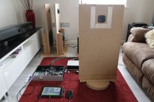
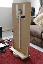
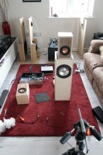
Now made the 20" x 38" baffle with the initial 2" cut around the 14cm x 21cm inner baffle. As 6mm MDF has been used, a second 12mm 14x21cm baffle [glue currently drying] has been added, will also need a removable rear brace going from the bottom of the 'tongue' to the main baffle... This is for the Vifa unit.
Will do the off-axis measures of the F/Pro 4FE35 [20" x 38" baffle] this weekend, and hope to make a start on the Experimental Baffle next week.
|-O-|
Now made the 20" x 38" baffle with the initial 2" cut around the 14cm x 21cm inner baffle. As 6mm MDF has been used, a second 12mm 14x21cm baffle [glue currently drying] has been added, will also need a removable rear brace going from the bottom of the 'tongue' to the main baffle... This is for the Vifa unit.
Will do the off-axis measures of the F/Pro 4FE35 [20" x 38" baffle] this weekend, and hope to make a start on the Experimental Baffle next week.
Measures made with REW so far...
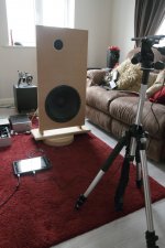
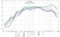
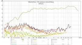
First up the Faital Pro 4FE35 mounted on the 20" x 38" OB... placement 32" up and 2" of centre. Measured axis from 0* to 90* in 15* increments at 1m. Measurement direction was toward the inner edge [shorter side] of the OB and at 80dB target. Speaker placement was equidistance from both side and rear walls in my main room, ~1.6m. 1/3 smoothing to make it easier to read.
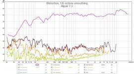
Of note, in the 500Hz to 5KHz range, THD is level at ~0.2% [-50dB] up to 80dB, with each 5dB increase hereafter there's a corresponding THD increase of ~5dB. However, only tested this at 85dB and 90dB. Also, switching from the TPA3116D2 [£12] to 'The Wire' LPUHP [£400] didn't alter the measurements in any way, FR, IR and harmonics all recoded the same.
Attachments
Last edited:
Then the test baffle with Vifa TC9FD... initial 2" cut-out and on-axis at 1m, 85dB target level.
Will play with ARTA today and tomorrow, so hopefully can start to measure and produce the polar response diagrams during the week... what SPL & frequency are we going for?
Will play with ARTA today and tomorrow, so hopefully can start to measure and produce the polar response diagrams during the week... what SPL & frequency are we going for?
Attachments
Last edited:
Great progress there Paul! The 4FE35 looks pretty good and I like what you have with the TC9 and cutout. I aim for 80 dB sound level on my measurements as that is typical high of what I listen at. 90 is good for checking distortion at higher drive levels. For polar plots I think freq where imaging are important are 500, 1000, 2000, 4000 Hz. If possible 8000 and 16000 Hz are useful too.
Awesome
That is awesome. I like the idea of reuse, recycle, up use speakers. And when your done the kids can play in them. No really nice speakers. I love to see creative people let er rip.Edit: latest results with 6 driver slot loaded woofer - see post 67.
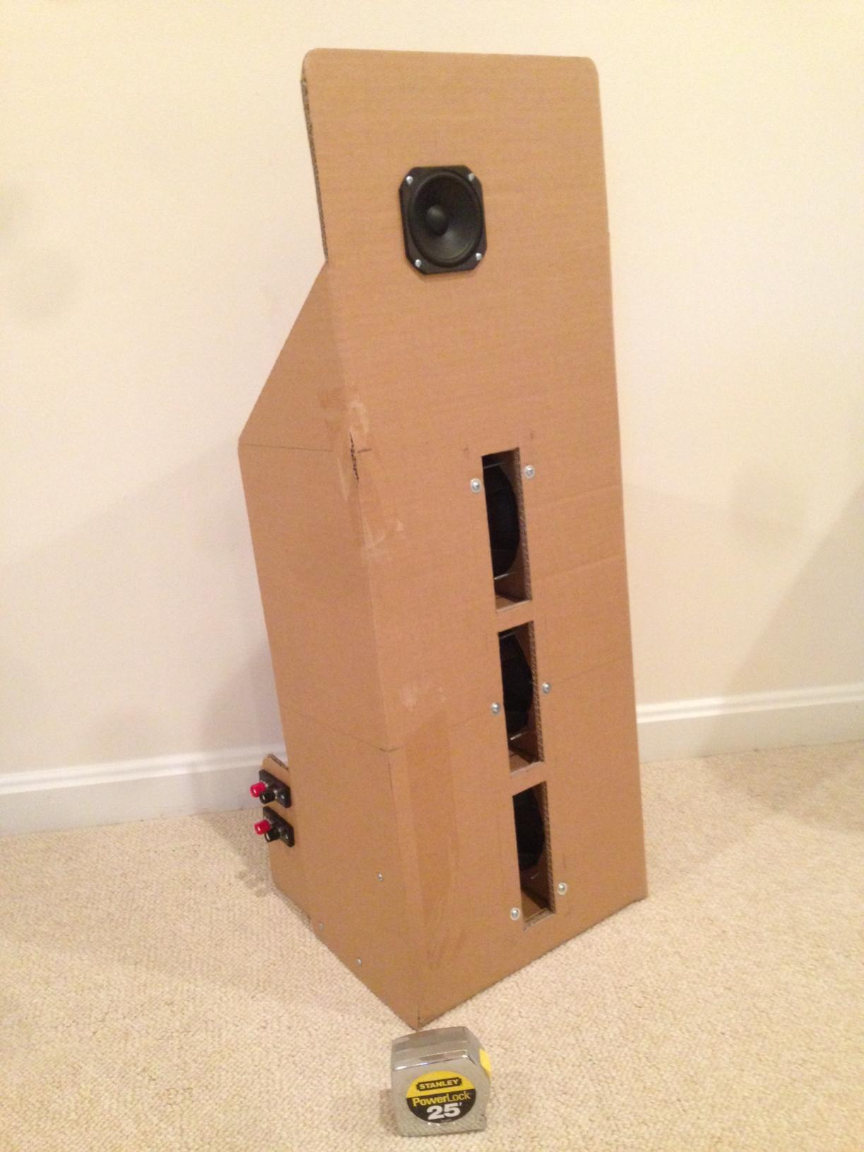
Having a bunch of Vifa TC9FD's in hand from when they had the sale for $10 ea, and a few more of the PE 6.5 in polycone woofers (part 299-609) for $4.88 ea lying around... I thought I should try a FAST open baffle, that can be made in less than 1 hr. Having measured both of these drivers in a 24 in x 36 in cardboard baffle before, I knew they had very flat responses, and being high Qts drivers would lend themselves to an OB. I also happen to now have a miniDSP to handle the XO and EQ duties, and I planned to bi-amp them. I am convinced that messing with huge inductors, and huge poly film caps for a passive XO will end up costing just as much as a minDSP and a pair of class D amps.
I happened to have some double-wall corrugated cardboard on hand that measured 12 in x 18 in. Guess what, that is now my OB baffle size. I had some more cardboard that I used to make some wings and the stand for the baffles. These ended up as 8 in deep at the base and going to 3 in deep 15 in up. I gave a tilt backwards to add stability and aim it up. The 6.5 in woofer is mounted 5 in from the bottom at the middle. The Vifa fullrange is mounted 5 in from the top and 4.5 in from one of the edges. I made it asymmetric to reduce diffraction. I added a 2.75 in deep cross brace on the back that will also come in handy for the binding posts. Everything was cut and tacked with a few points of hot melt and glued with Titebond at all seams. Cutting and gluing took 30 minutes. Screwing the drivers in and adding crimped connectors took another 15 minutes. Waiting for the glue to dry took 3 hours.
I tried running both drivers in parallel and full range to see what it sounded like - just a terrible mess. I then connected the drivers in a bi-amp configuration and driven by the miniDSP with a 24 dB/oct XO at 300 Hz.
The miniDSP setup took 15 minutes. Taking a measurement with the mic showed that it was pretty good but had a few minor dips and peaks that were easily EQ'd out. The bass extension is natural - no EQ'ing needed - it really does go to 50 Hz with the modest wings.
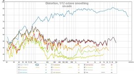
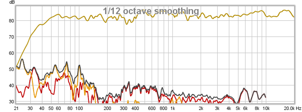
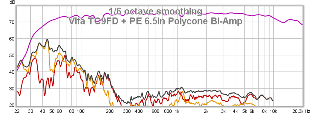
Here is the frequency response and distortion - nice flat response and low THD from the Vifa above 300 Hz. Below 300 Hz, the 6.5 in driver's cone excursion is starting to get taxed and hence THD goes up. Adding more woofers will reduce excursion and reduce THD. If I had more drivers, I would have used two in series for 8 ohms.
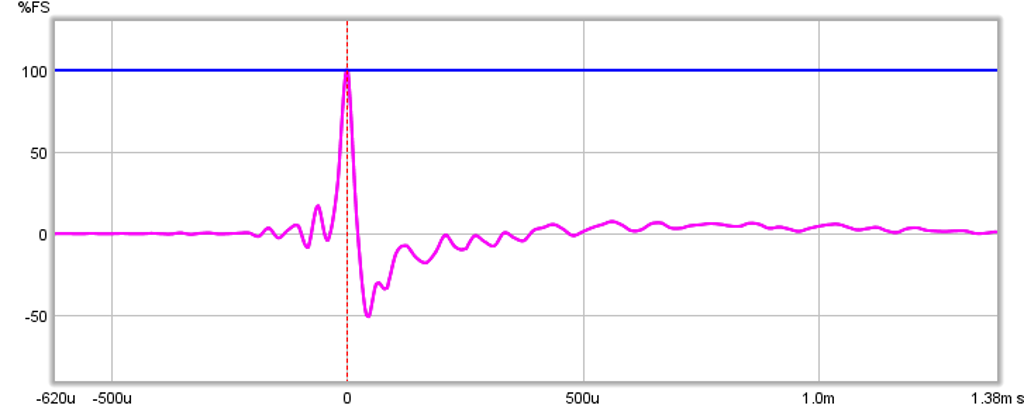
Here is the impulse response - doesn't get much better than this.
So how does it sound? Fantastic! It has some very nice clean dynamics capable of reproducing fast transients and percussion. It doesn't go very loud as the Vifa is nominally 85 dB at 2.83V but perfect for near field or low level listening. The sound stage is what is perhaps the best part - very wide and I can close my eyes and pinpoint the location of the singer, the instruments, and where they are positioned on the stage.
Anyhow, not including glue drying time, all this was done in about 90 minutes. Cost is $20 per speaker including binding posts. Now that is a cheap and fast FAST that sounds great and measures well.
Bojonjovi,
Thanks! Until folks try cardboard or foam core speakers they won't believe they can sound great. The OB definitely can use more bracing or a stiffer 1/4 in ply facing though. Most of my other builds vibrations from sheer force of drivers has not been a problem but with six drivers ganged together there is a lot of sound pressure.
Thanks! Until folks try cardboard or foam core speakers they won't believe they can sound great. The OB definitely can use more bracing or a stiffer 1/4 in ply facing though. Most of my other builds vibrations from sheer force of drivers has not been a problem but with six drivers ganged together there is a lot of sound pressure.
FC is fun to play with and now I have a pair of TC9FD's may try a few of the builds out ... DCR and Nautaloss being the main two and maybe the Mini Karlsonator
|-O-|
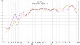
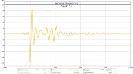
Finally fitted the Alpair 7.3 into the Plant 10 designed mMarS sealed enclosure, needed to play around with the filling to try smooth out one or two peaks & more tweaking still required. The FR is quite nice and THD fairly good but could be better...
A7.3 measure very close in both the mMarS and FH3 ... the measurements of the 4FE35 so far have proved slightly better for the same SPL... Would like to try the A7's mounted on an OB at some point.
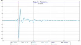
One area I'm not happy with is the A7.3's IR, the second period of peaks looks to be from internal reflections? Certainly not as clean a response as with the OB's
|-O-|
Finally fitted the Alpair 7.3 into the Plant 10 designed mMarS sealed enclosure, needed to play around with the filling to try smooth out one or two peaks & more tweaking still required. The FR is quite nice and THD fairly good but could be better...
A7.3 measure very close in both the mMarS and FH3 ... the measurements of the 4FE35 so far have proved slightly better for the same SPL... Would like to try the A7's mounted on an OB at some point.
One area I'm not happy with is the A7.3's IR, the second period of peaks looks to be from internal reflections? Certainly not as clean a response as with the OB's
Attachments
Last edited:
The internal reflections in a rectangular box are to be expected as not as good as OB, a curvy wall DCR box, or a Nautaloss. That is great to hear that the 4FE35 seems to be a great performer. The performance to price ratio is very good on that one. Do you find that it has sufficient xmax? The A7 has 4mm vs 2.7mm on 4FE35. But maybe with a 5dB efficiency gain you don't need as much cone displacement?
If you want to play with foam core give the mini Karlsonator a try. That speaker will make a believer out of anyone who hasn't tried either the Vifa or FC.
If you want to play with foam core give the mini Karlsonator a try. That speaker will make a believer out of anyone who hasn't tried either the Vifa or FC.
Will play with ARTA today and tomorrow, so hopefully can start to measure and produce the polar response diagrams during the week... what SPL & frequency are we going for?
@ BMS,For polar plots I think freq where imaging are important are 500, 1000, 2000, 4000 Hz. If possible 8000 and 16000 Hz are useful too.
"bad" and "good" polar patterns of an open baffle are structured in an octave rhythm. In your Faital example 500, 1000, 2000, 4000 ... Hz happen to deliver the nice pattern set. 375, 750, 1500, 3000 ... Hz would represent the bad set. Hope you can follow my explanation:

On top you see the frequency response of a circular open baffle with a driver in the center, where the baffle radius is 8 times the cone radius of the driver (b=8a). The diagram is taken from fig. A3-5 in Electro-acoustic models
If you are brave and really curious, you can learn the innards of that diagram from Linkwitz or the Tim Mellow link below that diagram. But you will understand my rambling without that.
The lower frequency response is yours. Your OB is pretty much equivalent to a circular baffle with ~8 times the radius of the Faital. And ka=1 in the upper diagram is almost identical to 1 kHz in the lower one. Albeit your OB is rectangular, has the driver set off, is measured to one side only and smoothed to 1/3 oct, we can easily identify certain regions (red lines from left to right):
- start of the dipole rolloff
- first dipole null
- second dipole null
- start of driver beaming
Now compare the 500, 1000, 2000 ... Hz pattern with the dipole nulls. You will avoid them quite elegantly. 750 and 1500 Hz will show where the dipole pattern "goes wrong". So please let us see both versions.
Regarding Arta polars:
- Please uncheck the "center peak of impulse response" square (above the "dB" bar) in the "Impulse Response Measurement" window. This will give you low ms values in the x-axis.
- Please show first impulse measurement diagrams of your Arta polar trials, so that we can discuss the best gating window for the polar diagram tool. 0, 45, 90° would be perfect.
Thanks X, from the measurements [and some mechanical sympathy] I think the 4FE35 has the upper hand again being 5dB more efficient, plus having a slightly higher power rating. As a single full range driver, I'd feel more comfortable pushing the 4FE35 to 95-100dB, it'd be like torture to push the A7.3 to or above 95dB.
Rudolf, thanks for the great info. I'll certainly post an initial polar response based on 0, 45, 90° and we can take it from there... Had a first run trough with ARTA, set-up the UMIK-1 and first measure. Next step is to buy the licence, the demo doesn't allow saving or loading of files
For the full polar plot, what intervals are used, 5° or 10°?
Last edited:
For the full polar plot, what intervals are used, 5° or 10°?
Fantastic progress Paul!!
The best looking plots are at 5 degrees, although you can get a decent idea using as course as 15 degree increments.
Z
Sorry, I wasn't asking for 0, 45, 90° polars - just impulse responses.I'll certainly post an initial polar response based on 0, 45, 90° and we can take it from there...
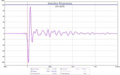
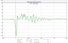
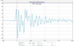
Just for example a 90° and 0° response measurement of mine:

I put the start of the window/gate (click on left mouse button) just in front of the impulse, the end (click on right mouse button) just in front of the first significant reflection. Note that the gating of the Arta polar tool will only accept full milliseconds, so it doesn't make sense to be too picky in determining the gates.
You should make sure that all impulses start within your window. You should try to make the window as large as possible. Start and end values of the window are shown as "Cursor" and "Gate" below the diagram. I choose a 7 ms window for the 0° measurement. It ends just in front of the first reflection. Note how the 90° measurement has a first reflection starting at 5.5ms. You can also see the 7 ms reflection.
Ignore that 5.5 ms reflection if it only happens at large angles (60+°). You would only gate to 5.5 ms if you want to see the exact depth of the 90° dipole null.

Note how I use the "Gated" radio button in the "directivity data definition" window. Ungated analysis is easier for sure, but is always prone to distorted polars because of room reflections.
15° would be sufficient for a first overview, 10° is enough for all normal discussions. I never do 5° - it hardly makes sense in usual rooms because the room influence will probably mask/disturb the finest details anyway.For the full polar plot, what intervals are used, 5° or 10°?
- Home
- Loudspeakers
- Full Range
- Cheap and FAST OB, Literally