Certainly can ") will be towards the end of this week before I can do the measures though...
will be towards the end of this week before I can do the measures though...
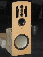
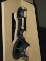
Just picked up the front & rear panels for the miniSharc enclosure, they look sweet
Have the Sharc to case-up and also gluing the sealed mMarS for the A7.3... bit awkward as the driver's rear brace needs fine tuning before it goes in permanently.
|-O-|
Did have a sheet of MDF in the parents garage, just about big enough to make a single 20"x38" baffle... I want to give the 'Tounge' cut-out a go around a 14cm x 21cm inner baffle. How is the increasing size of the cut-out to be done, height & width increase or just width with a fixed height?
will be towards the end of this week before I can do the measures though...Just picked up the front & rear panels for the miniSharc enclosure, they look sweet
Have the Sharc to case-up and also gluing the sealed mMarS for the A7.3... bit awkward as the driver's rear brace needs fine tuning before it goes in permanently.
|-O-|
Did have a sheet of MDF in the parents garage, just about big enough to make a single 20"x38" baffle... I want to give the 'Tounge' cut-out a go around a 14cm x 21cm inner baffle. How is the increasing size of the cut-out to be done, height & width increase or just width with a fixed height?
How is the increasing size of the cut-out to be done, height & width increase or just width with a fixed height?
Paul,
If I were designing the experiment, I would incrementally increase the width of the slot both below and to either side of the baffle, by say 0.5 inches (1cm) each time, i.e., leaving the baffle around the FR driver the same size (Rudolf's baffle looked great). I would guess a 2" wide slot would be a good starting point. (see diagram below)
Then perform a directivity vs frequency test after each expansion of the slot. Obviously you can listen after each cut, but then you have to re-equalize on axis after each cut and it's really hard to know if you are making the directivity more uniform or you just like a given set of music better with the new power response. (When you use the directivity measurements tools in ARTA, for example, it allows you to normalize the plots to on-axis response, so there is no need to eq. after each time you cut.)

Baffle with Cut-outs (to scale)
Integrating Rudolf's 14x21cm test baffle
WARNING: This is tedious. (And, we would all be grateful to see the results.)
You need some sort of turntable to make this reasonable: check out the one I produced an instructional for: http://www.diyaudio.com/forums/multi-way/252593-novel-open-baffle-construction-techniques-6.html Post #58 & #59
Love to see more close-up photos of your current build-
Z
Z,
I have a question of whether or not one needs the extra baffle beyond the cutout? I know that is the test you are seeking by varying the cutout slot width - the extreme limit is a very wide cutout (or no extra baffle edge). Are you trying to preserve bass extension but at same time improving the polar response?
X
+1 on the usefulness of this if Buildmesomething can make the measurements. We would all indeed be very grateful.
Z,
I have a question of whether or not one needs the extra baffle beyond the cutout? I know that is the test you are seeking by varying the cutout slot width - the extreme limit is a very wide cutout (or no extra baffle edge). Are you trying to preserve bass extension but at same time improving the polar response?
X
My goal has been multi-fold (I have not had time to publish all of my cutout trials, but there have been plenty.) First, I like the aesthetics of the rectangular baffle, especially the idea of stretching fabric over them so they look like an electrostatic or some other exotic panel. So, I am trying to keep the directivity constant while keeping a clean look. I think the narrowing/odd-shaped baffle looks ugly. Although a few folks don't seem to mind the Linkwitz 521 design, no one is giving it high praise aesthetically. There is simply no denying there are "two piles of equipment" in the room. John K. has done much better with his frame-grill arrangement hiding the "pin head baffle" of his NaO Note design.
Second, yes, has been the idea of using the remainder of the baffle for bass extension because at some point (as Rudolf has pointed out) the cutouts are opaque to the longer wavelength of lower frequency radiation.
Third, I was also hoping to use cutouts to eliminate the "suck-out" null when constructing MTM designs. This null in MTMs occurs at wide vertical angles below the crossover frequency; simulations show that the slots reduce it and so did testing; the dipole cancellation around these cutouts eliminates the interference between drivers at wide vertical angles. Here's an example that worked (but the dipole tweeter did not):
.jpg")
.jpg")
Slots for Cancelling the MTM Null
(Check out the vintage scopes!)
I also must admit that I liked the idea purely because I thought it was novel and unique. I think we are all looking for a diamond we can produce with a saber saw (or an X-acto knife), a few bits of roofing, tin-foil and glue, etc.
Z
Again, thanks Z et al... I've pencilled in the measurements on the MDF, plus have a few bits that I can use to make a 'Lazy Susan'. Hope to have the cutting & basic set-up ready over the weekend.
Downloaded ARTA but will need to get the licence once ready to proceed.
Let you know if I have any problems... I'll start with the 4FE35 at various off axis measures [with REW]... then move over to the Vifa TC9 in the 14x21 baffle [with ARTA]
Measured Faital Pro 4FE35 in the current OB at -30, -25, -20 & -15dB. Included the harmonics at -15dB [90dB SPL]... again no EQ, on-axis at 1m, OB in listening position 5' from rear wall. LP & HP XO at 200Hz LR24dB/oct.
Paul
Attachments
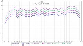
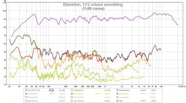
Yes, not bad for a $25 driver at all. The TC9 is half the price but I bet due to the lower efficiency will have higher HD at 90dB of about -30dB is my guess vs the -40 to -45dB HD you are getting with the 4FE35. It will be interesting to see how all this fares against the premium A7.3.
That is a cool looking MtM with a Vifa. Tell us more - do you have meas of the suck out reduction?
Sorry I went mute for a few days. I wrote a response and then must have closed the window before hitting "Submit".
The MTM photo is a couple of years old. My measurement techniques were not as good then. (I was moving the mic to to measure off-axis instead of using a turntable, so it was too difficult to produce full directivity plots.) I do, however, have a very clear memory that the predicted null (~2kHz) at 1m, 45 degrees vertical off axis was absent. I just abandoned this design because I could not come up with a small dipole tweeter that would fit between the two Vifas (without spreading them too far). The baffle is dismantled now.
Again, thanks Z et al... I've pencilled in the measurements on the MDF, plus have a few bits that I can use to make a 'Lazy Susan'. Hope to have the cutting & basic set-up ready over the weekend.
Downloaded ARTA but will need to get the license once ready to proceed.
Let you know if I have any problems... I'll start with the 4FE35 at various off axis measures [with REW]... then move over to the Vifa TC9 in the 14x21 baffle [with ARTA]...
Paul
Paul,
I will be skiing in Canada next week, leaving tomorrow morning. Staying up on a mountain. If the internet is good, I'll probably continue to post, otherwise I'll rejoin the discussion next weekend. I can answer simple questions with respect to ARTA, but I use it infrequently enough that I have to learn it again each time (following clues I left myself).
Really appreciate you investigating this!
Z
P.S. Here's my first use of cutouts- a pair in 2009, built for a college fraternity house. No directivity measurements, but they measured great on axis and the open sound kept me coming back to OBs. Check out the coils the boys hand wound for the passive crossovers used in the dipole section (+/- 2dB 120Hz-20kHz).
Attachments
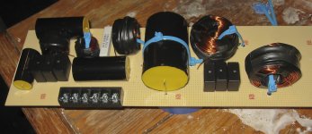
That is a cool speaker! How did the pleated diaphragm dipole tweeter work out?
That's a Neo3PDR tweeter- very clear/fast. They were much less expensive at the time.
I would like to hear these speakers again, but the boys burnt them up (more than once). The diaphragms were beer proof Al, but the voice coils could not withstand beer induced enthusiasm with the volume control.

Perhaps I should retrieve them and give them some TLC?
Amen Brother.. I think we are all looking for a diamond we can produce with a saber saw (or an X-acto knife), a few bits of roofing, tin-foil and glue, etc.
Z
Paul,
If I were designing the experiment, I would incrementally increase the width of the slot both below and to either side of the baffle, by say 0.5 inches (1cm) each time, i.e., leaving the baffle around the FR driver the same size (Rudolf's baffle looked great). I would guess a 2" wide slot would be a good starting point. (see diagram below)
Then perform a directivity vs frequency test after each expansion of the slot. Obviously you can listen after each cut, but then you have to re-equalize on axis after each cut and it's really hard to know if you are making the directivity more uniform or you just like a given set of music better with the new power response. (When you use the directivity measurements tools in ARTA, for example, it allows you to normalize the plots to on-axis response, so there is no need to eq. after each time you cut.)
View attachment 408472
Baffle with Cut-outs (to scale)
Integrating Rudolf's 14x21cm test baffle
WARNING: This is tedious. (And, we would all be grateful to see the results.)
You need some sort of turntable to make this reasonable: check out the one I produced an instructional for: http://www.diyaudio.com/forums/multi-way/252593-novel-open-baffle-construction-techniques-6.html Post #58 & #59
Love to see more close-up photos of your current build-
Z
I don't know if you guys have seen the terrific modeling work by Onni - he uses a package called COMSOL Multiphysics which is a 3d FEM solver and can do some amazing things. He can definitely model this baffle cutout trick.
Here is what Onni did on the Cornu BLH speaker: http://www.diyaudio.com/forums/full-range/225622-ever-think-building-cornu-spiral-horn-now-you-can-149.html#post3871894


Yes, bring them back from the dead and keep them safe at home. It is a mistake to let party boys have an amp that is more than speakers can handle. What were you using for mids?
Well the frat paid for all the drivers and they did a lot of assembly, so I don't feel so bad about it. The drivers were 2 Dayton RS100-8T, an RS225-4, the BIG NEO3-PDR and a 15 in Rockford-Fosgate sub in a sealed box. FYI the Dayton RS100 mounts the same as the Vifa TC9; they have more Xmas, super low distortion but have more severe breakup above 12kHz.
Z
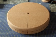
Nice turntable. I recall Z has some pretty easy plans for a turntable using two sheet of wood and a bolt. I think the trick is to make the table big enough so that you can put the speaker back far enough so that the axis of rotation goes through an imaginary vertical line on the front surface of the baffle rather than wherever it ends up being if you placed the speaker centered on the turntable. This is what I liked about Z's idea - it is big and roomy to put speaker anywhere you want.
- Home
- Loudspeakers
- Full Range
- Cheap and FAST OB, Literally