How would this speaker workout ? Not $4 each though
https://www.parts-express.com/fender-8-full-range-speaker-8-ohm--299-079
https://www.parts-express.com/fender-8-full-range-speaker-8-ohm--299-079
... Use 4 per side in slot loaded config.
Is this 8 per speaker / 4 per side ?
4 per speaker is same as single 15 in woofer, more is better if you have room and can afford it. 8 per side should be more bass if you like impact of dual 15 in drivers.
Nelson Pass used 6 x 8 inch woofers and that worked well with a high efficiency Lowther fullrange top. You get an odd 6 ohm impedance though. 8 x 8 gets you 8 ohms or 4 ohms. The height of 4 stacked slots is only maybe 40 inches which isn't bad if you want the fullrange at ear height.
Go for 8 if you can afford it
Last edited:
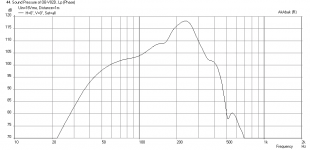
Here is what qnty 8 of the above Fender 8 in drivers can do in a 16 in wide x 40 in high main open baffle with slot loaded chamber (slot box is 6 in wide x 10 in deep x 32 in high with 2.5 in wide x 32 in high slot). This is driven to xmax at 16 volts with drivers in parallel series for 4 ohms nominal impedance (with 35 Hz -24dB/oct high pass filter in place to reduce cone excursion at low end). As this is at xmax, you will need to apply negative EQ'ing to flatten the response. A reasonable max bass extension (0 dB point) of 90 dB at 36 Hz is possible due to xmax limit. The -3dB point is about 33 Hz.
First plot: this is with speaker placed about 45 in from back wall and 70 in from side wall.
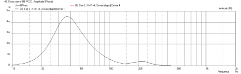
Second plot: cone excursion at 16 volts drive
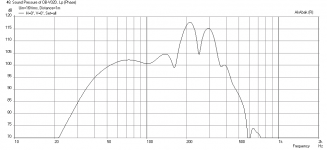
Third plot: same drive voltage but with speaker placed 60 in from back wall and 60 in from side wall
It looks like setting XO to the full range at 250 Hz should work.
First plot: this is with speaker placed about 45 in from back wall and 70 in from side wall.
Second plot: cone excursion at 16 volts drive
Third plot: same drive voltage but with speaker placed 60 in from back wall and 60 in from side wall
It looks like setting XO to the full range at 250 Hz should work.
Attachments
Last edited:
...Great feedback Z, will certainly give the U-shaped cut-outs a go
With respect to the cutout size, the 14x21cm baffle that Rudolf tested (post #30 on page 3 of this thread) looks perfect, great directivity results:
Rudolf's Directivity Results
But we should ask him what his baffle thickness was.
The "tongue" is the shape remaining after the cutout
So I would suggest making the "tongue" 14x21cm (no use reinventing the wheel- Thanks Rudolf!), with the 21cm dimension from the top of the baffle to the bottom of the slot. The rounding of the "tongue" I showed was just an idea. The rectangle may be better. As for the cutout width, I think 2 inches would be minimum.
If Rudolf is listening: What was the thickness of the baffle and what is the vertical dimension to the center of the speaker?
Z
New Bi-Amp Active XO setup
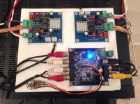
I just got a couple of new TPA3116D2 amp boards the other day (the YBDZ 2.0 from Aliexpress) and wired them up with the miniDSP for my new active XO bi-amp setup. To test it out, I tacked them onto a foam core board as shown. Once I play with it and see that it works I may put it all in a box. The amps are 50 watts/ch x 4 channels. It sounds great and is very compact.
I just got a couple of new TPA3116D2 amp boards the other day (the YBDZ 2.0 from Aliexpress) and wired them up with the miniDSP for my new active XO bi-amp setup. To test it out, I tacked them onto a foam core board as shown. Once I play with it and see that it works I may put it all in a box. The amps are 50 watts/ch x 4 channels. It sounds great and is very compact.
Attachments
X - I've not measured Vas but its spec-ed at 2.7 cubic feet. 2mm xmax ain't much but maybe with enough - ?
Peerless approximate range on axis

Peerless qts, fs without break-in

w8-12t-12p published stuff
voice coil diameter = 1 inch
Resonant Frequency (Fs)43 HzDC Resistance (Re)10.9 ohms
Voice Coil Inductance (Le)1.93 mHMechanical Q (Qms)2.57
Electromagnetic Q (Qes)0.72Total Q (Qts)0.56
Compliance Equivalent Volume (Vas)2.7 ft.³Maximum Linear Excursion (Xmax)2 mm
Peerless approximate range on axis
Peerless qts, fs without break-in
w8-12t-12p published stuff
voice coil diameter = 1 inch
Resonant Frequency (Fs)43 HzDC Resistance (Re)10.9 ohms
Voice Coil Inductance (Le)1.93 mHMechanical Q (Qms)2.57
Electromagnetic Q (Qes)0.72Total Q (Qts)0.56
Compliance Equivalent Volume (Vas)2.7 ft.³Maximum Linear Excursion (Xmax)2 mm
Last edited:
btw X, can you see any potential advantages to this arrangement where there's a K-slot on either side of the baffle but one slot is inverted? (the front of each cone faces the beginning of the Karlson-slot)
An externally hosted image should be here but it was not working when we last tested it.
A K slot on either side of a W frame dipole sub huh? Well I know the width of a slot in the slot loaded dipole sub affects the peak height of the resonance freq (circa 250 Hz in the plot of FR in the sims above) of the a lot chamber. Maybe the smooths that out and requires less EQ? Interesting concept - how does it sound?
With respect to the cutout size, the 14x21cm baffle that Rudolf tested (post #30 on page 3 of this thread) looks perfect, great directivity results:
Rudolf's Directivity Results
But we should ask him what his baffle thickness was.
The "tongue" is the shape remaining after the cutout
So I would suggest making the "tongue" 14x21cm (no use reinventing the wheel- Thanks Rudolf!), with the 21cm dimension from the top of the baffle to the bottom of the slot. The rounding of the "tongue" I showed was just an idea. The rectangle may be better. As for the cutout width, I think 2 inches would be minimum.
If Rudolf is listening: What was the thickness of the baffle and what is the vertical dimension to the center of the speaker?
Z
Z,
This "Tongue" baffle cutout is interesting - I will give it a try once I get a turntable to do measurements. As it is I move the mic tripod and that is a pain but works well as I don't have an anechoic chamber so rotating the speaker may affect measurements more vs mic movement? Although if I gate the effects of room interaction can be reduce as we are concerned more about 500 Hz on up.
Thanks for the tip on Rudolf's work. He is certainly a master of the OB.
This was just an experiment. The baffle was 4 mm plywood. Usually I use 16-18 mm plywood, but I wanted to avoid routing the driver cutout.If Rudolf is listening: What was the thickness of the baffle and what is the vertical dimension to the center of the speaker?
Even a 12 mm baffle would hardly have changed anything in that diagram.
Driver is mounted 15,5 cm from the bottom of the baffle. But don't worry about 2 or 3 cm more or less, if you keep the distance from the driver center to the baffle top fixed.
Always keep the mic and the turntable at fixed positions in the room. Preferably as far from the walls as possible/sensible. The only part moving should be the rotation of the turntable. You can't avoid reflections from the walls. But those will only change their strength, but neither direction nor timing. Gating the measurement is your friend there.Z,
As it is I move the mic tripod ... ... so rotating the speaker may affect measurements more vs mic movement?
Moving the speaker or the mic through the room will move them through the room modes. And gating helps absolutely nothing against room modes.
I believe the gap has to be wider than a wavelength - or at least 1/2 of it. If it is narrower, it will be as effective as a cattle grid wrt an elephant walking by.As for the cutout width, I think 2 inches would be minimum.
In that logic a 2" gap would disappear/close for anything lower than 5 kHz.
I believe the gap has to be wider than a wavelength - or at least 1/2 of it. If it is narrower, it will be as effective as a cattle grid wrt an elephant walking by.
In that logic a 2" gap would disappear/close for anything lower than 5 kHz.
Which would also mean that for it to be effective down to 500hz, it would have to be 34 cm (or approx 13.5 inches for the SI challenged
).If that's the case, then the gap is only a viable option for tweeters...
There are thousands of 2-ways in the "box" world where the "woofer" has to reach up to 2 kHz. And most owners of those boxes believe that it works.Which may mean than a 2-way will not work because the cutoff is now too high for the woofer to reach up to.
All those wide baffle dipoles work in a certain way. They just are compromises with a different focus. You can have a nice dipol pattern, but then you might worry about difficult crossover points. Or you can have an easy crossover, but with a compromised dipole pattern. You can't optimise both at the same time with a 2-way dipole.
- Home
- Loudspeakers
- Full Range
- Cheap and FAST OB, Literally