the distortion math is from the Taylor series expansion of tanh under the assumption that the mirror's doubling of the diff pair gm at the VAS input reduces the required signal in the diff pair to ½; the n-1 power instead of n comes from dividing by the signal once to normalize the distortion
For a power amp though, if one replaces the resistive load of the input stage with a current mirror, the resultant doubling of the GBW could cause instability. So it's normal to double the input stage emitter degeneration to put the input stage gm back to what it was without the current mirror and keep the GBW constant. This makes the distortion computation less straightforward.
Last edited:
For a power amp though, if one replaces the resistive load of the input stage with a current mirror, the resultant doubling of the GBW could cause instability. So it's normal to double the input stage emitter degeneration to put the input stage gm back to what it was without the current mirror and keep the GBW constant. This makes the distortion computation less straightforward.
I almost mentioned that in the previous post. This is why you can't just bung a CM onto your dodgy Citation clone, listen, and then declare, unequivocally, that a CM "sounds bad"

I almost mentioned that in the previous post. This is why you can't just bung a CM onto your dodgy Citation clone, listen, and then declare, unequivocally, that a CM "sounds bad"
Yeah. In fairness, I think jcx is thinking about low-power circuits, where one can crank up the GBW at will. But power amps require more conservative design as you know.
Yes, I know what you're saying
You're lucky I'm quoting you 30 seconds late!
Member
Joined 2009
Paid Member
This is (mostly) why an EF buffer for the VAS gives such a dramatic improvment to linearity - it raised the VAS input impedance further.
In this kind of topology the maximum possible slew rate is determined by the current that the LTP can deliver to Cdom. With a current mirror on the LTP, this current is doubled.
77That's exactly where I was heading with TGM...Harry88 put the EF buffer before the VAS instead of after it !
http://www.diyaudio.com/forums/solid-state/146015-new-amp-harry-77-a-5.html#post1888794
The improved balance LTP balance obtained with a CM actually lowers the input offset voltage.
Regarding the VAS, this stage has local negative feedback provided by Cdom. If the VAS base is tied to the respective rail with a low value resistor the feedback via Cdom is reduced. Add a current mirror and the impedance at the VAS base is increased along with the local feedback provided by Cdom, and the VAS linearity improves. This is (mostly) why an EF buffer for the VAS gives such a dramatic improvment to linearity - it raised the VAS input impedance further.
Yes I am sure. The reason why the gm of the LTP is effectively doubed when a CM is added is because the current in each leg is utilised to provide push-pull drive to the VAS.
In this kind of topology the maximum possible slew rate is determined by the current that the LTP can deliver to Cdom. With a current mirror on the LTP, this current is doubled.
Speaking about the BW in my discussion I looked at the LTP and CM solely where the BW goes down because the summed Cob is more that tripled in a typical audio amplifier design, but... rereading your previous post I see what I missed and the magic word was Cdom and that is not part of the LTP or CM, yes of course if we are tossing in the Cdom AND the Miller capacitance AND taking the gain of the VAS stage into account we are of course talking about a different thing whereby the summed Cob of the LTP and CM is negligible no doubt about that. GK, you should have noticed that we were talking from a slightly different point of view!
Further linearising of the VAS stage due to the higher output impedance, let's look at it without an EF which was suddenly tossed in at some stage of this thread, yes it's true in conjunction with the added Cdom we get more "linearising" effect, but the same goes for the non-linear Miller cap, we get as well more "un-linearising" effects too, right? Now tossing in back the EF again it's a whole different thing which also goes for the non-CM loaded LTP, and as Andy also mentioned which also I had in my back head too we could crank up the bias current through the LTP but I didn't want to slightly offset the discussion suddenly by altering too many variables at one time.
Andy,
part of my reply above in words is just my view of the increased Cob in the LTP and CM stage alone, I'm not sure if that's what you were wondering about what I had in my mind and does it suffice as an answer to your question.
BTW, I will send you a PM
The CM may have some merits when it comes to certain aspects as gm doubling which in conjunction with the VAS Cdom/Miller cap roughly doubles the BW, increased PSRR etc.
Thinking about the very low Vcb over the mirror transistor in the CM configuration in a typical amplifier design the Early effect comes to my mind, that's not a very linear thing at very low voltages, read just for some day ago about a guy who used CM in some circuit where he charged a capacitor with a low current less than 1 mA and he wondered why the current change by 10% from the initial point of charging until the end of charging, now I can understand that is probably a large signal behaviour of the CM.
But some uses the CM inside the VAS stage where we also see large signal swing, as an example let's take a look at the first schematic under this link (the 2 x 2N5551 in the bottom of the VAS stage):
SymAsym5 - Project
Now how come some says a CM "sounds bad", is it because of a poor design and if so what is it that screws up the design?
Cheers Michael
Andy,
part of my reply above in words is just my view of the increased Cob in the LTP and CM stage alone, I'm not sure if that's what you were wondering about what I had in my mind and does it suffice as an answer to your question.
BTW, I will send you a PM
You've got mail. BTW, welcome back! It seems you've been gone for quite some time.
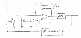
My questions were mainly rhetorical in nature. I was just trying to get you to think about it in a different way. With that in mind, I've attached a picture to try to clarify what I'm getting at.
A properly designed VAS should act in many ways like the op-amp integrator shown in the picture. The current source is meant to represent the diff amp output current for either the simple Rc case or the current mirror. Likewise, Cout and Rout represent the output impedance of the diff amp. For the simple Rc case, Rout=Rc and Cout~0. For the current mirror case, Rout is the output impedance of the current mirror and Cout is its output capacitance.
The open-loop gain of the integrator is assumed to be very large, so the voltage from the inverting input of the op-amp to ground is very small. So then, what effect does Cout have on the circuit?
Attachments
The open-loop gain of the integrator is assumed to be very large, so the voltage from the inverting input of the op-amp to ground is very small. So then, what effect does Cout have on the circuit?
A less conventional way to answer to your question is to apply the Miller theorem. The equivalent capacitances are then CinVAS=Cdom*(1+A) and the output as CoutVAS=Cdom where A is the VAS gain. If A is very large, obviously CinVAS will be much larger than the whatever previous stage output capacitance. This is an approximation that holds in 99.9% of the practical cases.
Last edited:
I’ll admit I didn’t initially think through the need to double the Cdom to keep the comparison equivalent on amp stability grounds
But after thinking about it I claim that I’m still at least ½ right that the current mirror’s doubling of the diff pair gm with doubled Cdom still results in input error/diff pair distortion reduction
For nonlinear (current) loads on the VAS the doubled Cdom gives ½ the output impedance from the VAS and a corresponding reduction in error to correct
Below the Cdom corner frequency with (parasitic) resistive VAS load, such as single ef output stages where the VAS sees amplifier load Z*hfe, the doubled gm doubles the loop voltage gain – and the corner frequency in “simple” discrete designs can often be in upper audio frequencies (the corner frequency does move lower by an octave)
2-pole compensation could move the compensation determined intercept with the DC gain limit to higher frequencies – often letting the increased V gain be effective over the audio frequency range
Last edited:
Yeah, I think you end up ahead with the current mirror almost no matter how you slice it - increase Cdom, increase input stage emitter degeneration, or some combination of the two. Having a large impedance "seen" looking back from the input of the VAS results in increased Miller loop gain, thus decreased VAS distortion. The only case I can see where it could degrade performance is if Cdom were much higher than optimum to begin with, and you doubled it to keep the stability constant. This might happen with a BJT input stage having no emitter degeneration both before and after.
There have been people who claimed "sonic degradation" from incorporating a current mirror, but there is no evidence that the effect this has on stability (doubling of the unity loop gain frequency) was properly considered and corrected for in those experiments.
There have been people who claimed "sonic degradation" from incorporating a current mirror, but there is no evidence that the effect this has on stability (doubling of the unity loop gain frequency) was properly considered and corrected for in those experiments.
Hi tiefbassuelvertr.
Thank for you reply.
The complete circuit is in the thread: my update lin topology
are you mean the circuits from
http://www.diyaudio.com/forums/solid-state/113088-my-update-lin-topology-4.html?
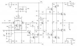
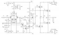
There are many circuits shows. Do you mean the circuits from the botton jpg files?
If yes, then I can say, that this circuit delivers very good simulation results. Unfortunately the simulation don't respect all parasitic effects through layout and mass management (GND management), and I know, by this circuit it isn't easy to develope a succesful layout. The internal open loop gain is very high. Not so the open loop bandwidth because two voltage gain stages in the NFB loop (Cdom is absolut necessary)
Also a good design is that you see at botton in the pdf file and it is less critical concerning the layout. This circuit was a diy project of the German hifi magazine "Stereoplay" arround 1987. The Autor was Mr. Günter Mania, the owner from todays brand AVM in Karlsruhe. Please note, that this amplifier runs in the inverted mode (input resistance = value of input serial resistor) If I haven't class A in the output stage (only 20-50mA idle current), I would prefer this topology, if the output stage is in the feedback loop.
Attachments
Speaking about the BW in my discussion I looked at the LTP and CM solely where the BW goes down because the summed Cob is more that tripled in a typical audio amplifier design, but... rereading your previous post I see what I missed and the magic word was Cdom and that is not part of the LTP or CM, yes of course if we are tossing in the Cdom AND the Miller capacitance AND taking the gain of the VAS stage into account we are of course talking about a different thing whereby the summed Cob of the LTP and CM is negligible no doubt about that. GK, you should have noticed that we were talking from a slightly different point of view!
Further linearising of the VAS stage due to the higher output impedance, let's look at it without an EF which was suddenly tossed in at some stage of this thread, yes it's true in conjunction with the added Cdom we get more "linearising" effect, but the same goes for the non-linear Miller cap, we get as well more "un-linearising" effects too, right? Now tossing in back the EF again it's a whole different thing which also goes for the non-CM loaded LTP, and as Andy also mentioned which also I had in my back head too we could crank up the bias current through the LTP but I didn't want to slightly offset the discussion suddenly by altering too many variables at one time.
Well it simply doesn't make any sense to evaluate the worth of a current mirror on the LTP without analysing its effect on the circuit as a whole.
As for buffering the VAS with an EF (NOT a Darlington), yes, the improvement in (VAS) linearity is still mostly due to the increased Miller loop gain. And what role do you think the EF has in combatting the effects of the VAS transistors Cob???
And we still have not ventured into the full impact of that CM on the LTP.
That increased Miller loop gain not only improves the VAS linearity, it also reduces the VAS output impedance at HF and more effectively pole-splits the effects of the driver input C. Ever wondered why the "Blameless" works so well with just a double EF power output stage?
Last edited:
Glen,
internal junction capacitances effectively short signal voltages from both input and output to ground, decreasing the bandwidth, gain, slew rate, introducing phase shift, causing distortion, oscillation and unwanted offset voltages. Dynamically, the nominal value of the constantly changing Cob can easily be multiplied by hundred. Feedback provided by extremely nonlinear parasitic capacitances does not linearize anything, and you don´t want signal voltages to develop over capacitances anywhere, especially not in voltage amplifying stages. By that logic devices with higher capacitances should be preferable, which is, of course, nonsense. Obviously, you consider gain as a primarily important factor for linearity, however, very far from the op-amp philosophy, I rather consider high-frequency performance as an important factor for linearity.
internal junction capacitances effectively short signal voltages from both input and output to ground, decreasing the bandwidth, gain, slew rate, introducing phase shift, causing distortion, oscillation and unwanted offset voltages. Dynamically, the nominal value of the constantly changing Cob can easily be multiplied by hundred. Feedback provided by extremely nonlinear parasitic capacitances does not linearize anything, and you don´t want signal voltages to develop over capacitances anywhere, especially not in voltage amplifying stages. By that logic devices with higher capacitances should be preferable, which is, of course, nonsense. Obviously, you consider gain as a primarily important factor for linearity, however, very far from the op-amp philosophy, I rather consider high-frequency performance as an important factor for linearity.
Glen,
internal junction capacitances effectively short signal voltages from both input and output to ground, decreasing the bandwidth, gain, slew rate, introducing phase shift, causing distortion, oscillation and unwanted offset voltages. Dynamically, the nominal value of the constantly changing Cob can easily be multiplied by hundred. Feedback provided by extremely nonlinear parasitic capacitances does not linearize anything, and you don´t want signal voltages to develop over capacitances anywhere, especially not in voltage amplifying stages. By that logic devices with higher capacitances should be preferable, which is, of course, nonsense. Obviously, you consider gain as a primarily important factor for linearity, however, very far from the op-amp philosophy, I rather consider high-frequency performance as an important factor for linearity.
What is this? Spambot?
"Glen,
internal junction capacitances effectively short signal voltages from both input and output to ground, decreasing the bandwidth, gain, slew rate, introducing phase shift, causing distortion, oscillation and unwanted offset voltages. Dynamically, the nominal value of the constantly changing Cob can easily be multiplied by hundred. Feedback provided by extremely nonlinear parasitic capacitances does not linearize anything, and you don´t want signal voltages to develop over capacitances anywhere, especially not in voltage amplifying stages. By that logic devices with higher capacitances should be preferable, which is, of course, nonsense. Obviously, you consider gain as a primarily important factor for linearity, however, very far from the op-amp philosophy, I rather consider high-frequency performance as an important factor for linearity. "
Lumba, I also don' get your view on this. I thought it was made clear in the previous posts, including from jcx that the linearity with the CM was improved (separately you cancheck out Self's plots with CM LTP load to verify this). Added to this is the improved slew rate and then on top of that you get additional loop gain. What's there to lose? Now, if you think loop high gain in itself is a bad thing and prefer lower loop gain - no problem, just load th e VAS down to ground and you can have your cake and eat it too.
Hi Bonsai,
Post #76 is about capacitances only, no current mirror inclusion.
Post #54 is a poor attempt to provide explanation for the sonic degradation due to the increase in voltage gain and fall in bandwidth, as a result of CM load representing high dynamic impedance.
No reason to be angry with me - this time. I agree with you 100%. I`ve suggested that many, many times, however by a resistor across the outputs, instead of to ground.Now, if you think loop high gain in itself is a bad thing and prefer lower loop gain - no problem, just load th e VAS down to ground and you can have your cake and eat it too.
Post #76 is about capacitances only, no current mirror inclusion.
Post #54 is a poor attempt to provide explanation for the sonic degradation due to the increase in voltage gain and fall in bandwidth, as a result of CM load representing high dynamic impedance.
- Status
- This old topic is closed. If you want to reopen this topic, contact a moderator using the "Report Post" button.
- Home
- Amplifiers
- Solid State
- CFP For The VAS