Thimios this looks über professional straight out from NASA's secret black budget audio research project, a golden diploma signed by Wernher von Braun is on the way and a schnapps Ouzo on top of it! 
It could of course be improved with thiagomogi's suggestion, in that case R17(21) are to be removed, but the diodes can be good to keep for protection.
btw, have you tested connecting any source to your amp and see if there is any hum still in the system? Perhaps at later stage can also try again add back the ground resistor between 0_source and GND(J5) and find out if it can work as intended.
Great work Thimios - thank you so much for being the pathfinder!
It would be helpful if you can show a photo of the PCB with where to cut traces and where to reconnect etc. If you could edit the original bare PCB photo that would be great. We have a lot of folks in the GB who would benefit from a detailed explanation.
It would be helpful if you can show a photo of the PCB with where to cut traces and where to reconnect etc. If you could edit the original bare PCB photo that would be great. We have a lot of folks in the GB who would benefit from a detailed explanation.
Here is what you ask about.Great work Thimios - thank you so much for being the pathfinder!
It would be helpful if you can show a photo of the PCB with where to cut traces and where to reconnect etc. If you could edit the original bare PCB photo that would be great. We have a lot of folks in the GB who would benefit from a detailed explanation.
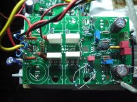
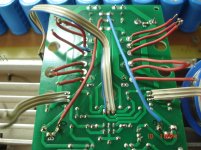
To the existing board cut these two points as in the first picture and solder two wires to the Power GND as in the second picture.
Do not forget the installation of two diodes following schematic IN POST#819 NOT AS IN FIRST PICTURE HERE.
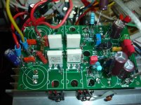
Please add the diodes as in the last picture.
Attachments
Last edited:
Thanks, Thimios. Did you change any resistors to get the correct VAS current etc?
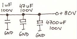
So you are saying use a larger than 100uF cap where the 4700uF used to be will cause problems? Sometimes more is not always better.
Btw, from your data what is the measured PSRR (at 50/60Hz and 100/120z)?
So you are saying use a larger than 100uF cap where the 4700uF used to be will cause problems? Sometimes more is not always better.
Btw, from your data what is the measured PSRR (at 50/60Hz and 100/120z)?
...So you are saying use a larger than 100uF cap where the 4700uF used to be will cause problems? Sometimes more is not always better.
Hi X you know I'm just hobby diy in this area so don't count on me
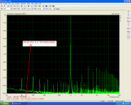
but wonder why when your sim showed better performance and many reported better sounding amps is seen with high value bank soldered onto amp PCB. Therefor can we suspect its simply because bypass capacitor is too small value in being only 0,1uF and that one needs to be at least 1uF or bigger maybe a 4,7uF or 10uF will do it. At this link advise is go higher values or don't bypass http://www.diyaudio.com/forums/powe...ing-psu-capacitors-effective.html#post1566979.Here is visual, say it happens because that 0,1uF is too small in value it spikes as those in 1-10mHz area say the yellow one. First red from left is optimal but also first blue and green is better than those spiky ones later so therefor its better go too large in value when gear to measure in actual situation is not available.
Swiss Goldmund amp famous for high sound quality use one elco and one film to bypass 4,7mF elco:
Have not seen member Mark Johnson post in this thread but could imagine he know some facts about bypassing or not and which policies is best for values when capacitors brand and dielectric is not stated in manual and we don't have laboratory gear to check in actual situation impedance.
If thimios is not too exhausted by now he could try the Goldmund one to see if 4,7mF works and if amp data gets even better than is at present.
Attachments
Last edited:
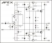
Please look the schematic on post#917 for VAS current.
The basic problem isn't on the big electrolytics but on the C16,C14.It is absolutely necessary to rearrange the GND added these 1N400X diodes AND power the VAS after the 10R.
The Shaan's recommendation<<Also put a trimmer with the negative side's 15K as well for best control over offset. These trimmers will be able to fine-tune VAS bias to some extent without changing VAS emitter resistor so you get two operations in control in one mod>>. is the final solution for VAS current adjust and offset setting on mod!
Last edited:
Thimios - the 15k with trimmer is that a 5k pot in series with existing 15k and use this to trim VAS current and DC offset?
Also, can you tell me what the PSRR is now with new arrangement? I wasn't sure where your 0dB mark was. I was getting some really small value (-120dB)? Seems too small.
Also, can you tell me what the PSRR is now with new arrangement? I wasn't sure where your 0dB mark was. I was getting some really small value (-120dB)? Seems too small.
VSSA copy, even with the same resistors values, not much to do around. Still mediocre SQ compared to the best commercial amps available.Not bad at all for a simple cheap CFA amplifier!

Why not add a circuit like this instead of a resistor for VAS and input?
This give me idea for F8R, thank you.
Regards
Attachments

 VSSA was an open project for the masses, track record of all the copies followed around the world are well documented by the Google. Few hundreds modules of mine traveled the globe, according to feedback there are many satisfied customers. My intention was to start promotion of CFA amplifiers since all what was present at that time in majority sites was classic Linn LTP topology. Master plan worked very well as you can see from the variety of threads evolved on DIY audio, including this one. Basic schematic is so tempting that once seen, one could not resist to try. What's best, the result is amazing compared to stakes involved.
Happy VSSA builds to all of you.


...I never said that an amplifier with the best measurements is the best sounding one.
I see what you did there!
This give me idea for F8R, thank you.
Regards
Hi Apex,
Very cool! Is that all it takes to add a cap Mx to protect the VAS and IPS? Can you show us how to size the cap and resistor? Is it basically setting the RC time constant to be well below AC line ripple of 50Hz/60Hz?
Would a BD139/140 be ok to use here or MJE350/340?
- Home
- Amplifiers
- Solid State
- CFH7 Amp