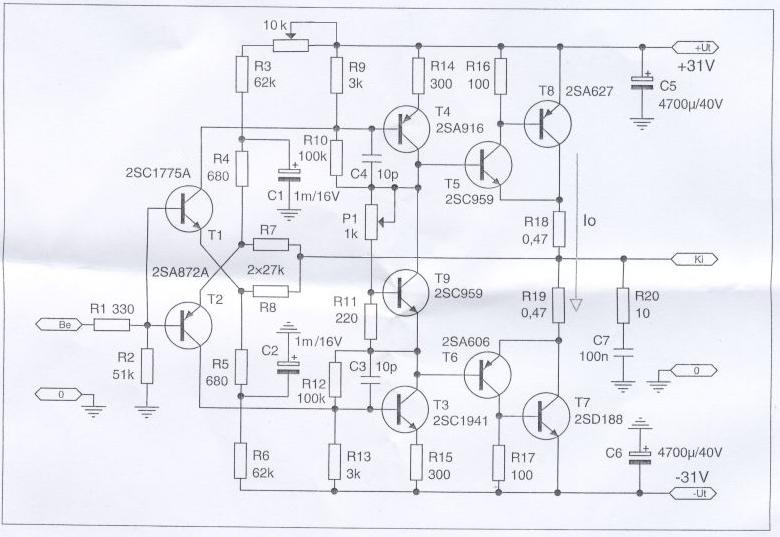
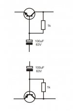
...That means, when the audio signal enters the VAS stage T3(T4), these transistors must have both base and emitter referenced to the same + and - rails, but when adding a 10R and another big electrolyte on the other end of the 10R, the VAS transistor has 2 different references with respect to the signal, this is suboptimal...
This is what was happening in the original layout. The VAS base-emitter 470R resistor was fed from the capacitor but the emitter 10R resistor connected to the dirty rail just before the filtering.
In my last attachment you can see the VAS's both emitter and base are referenced from the same points, that is the rail voltage at the supply pin of the decoupling capacitor to be added Just After the diode and the resistor (point A and B).
Also, as the signal at VAS bases are + and - referenced, I think it is even more important to keep the references steadiest and most free of hum for the VAS/input. Shorting the resistor will do the opposite.
...the amp schematics has gone through many iterations and some are representing proposals for improved modifications, it makes the discussion of the amp somewhat confusing...
Thimios is here to help.

I think we should wait for him to do all the tests and share his final smallest bunch of modifications on the CFH9 board that does the biggest improvements. I think everyone here is waiting just for that.
Last edited:
Shaan i must mention some strange things in the vas stage. Sometimes measuring the vas current in the 10R i see that isn't stable from the start to end, sometimes i see big difference . When i had tried 22K(R10,R11) i had seen 600mV d.c offset.The resistors are for creating a CDRC filter in the PS rail to filter out more ripple before powering VAS/input. The diode is added to prevent VAS/input PS rail from sagging during loud transients.
Guys,please wait until all issues has gone!
I will post an updated schematic and all the modifications.
Last edited:
When i had tried 22K(R10,R11) i had seen 600mV d.c offset
P1 trimmer should come in handy.
No.no i say about not well controlling offset ,550mV D.C OFFSET when trimmer is at the end.P1 trimmer should come in handy.
The same time voltage on R3,R2(47R)= EQUAL=100mV(2.1mA).
Last edited:
No.no i say about not well controlling offset ,550mV D.C OFFSET when trimmer is at the end.
That is because the trimmer is in a sub-optimum place to control the offset. But I guess this can not be repaired in the existing layout.
These are the three schematics in the first post that shows the right place for P1. In CFH9 PCB it would be in series with the 15K/18K resistors. I don't know why this wasn't done in the chosen schematic.
Also, as the signal at VAS bases are + and - referenced, I think it is even more important to keep the references steadiest and most free of hum for the VAS/input. Shorting the resistor will do the opposite.
Which schematics are we referring to now?
Yes indeed and I fully agree, we still need those R17(R21) 10R rails filtering resistors but moved to a location before VAS emitter and base reference points to keep it clean from OPS dirty voltage!

The same time voltage on R3,R2(47R)= EQUAL=100mV(2.1mA).
Current through these two resistors can't be and don't need to be perfectly equal in this amplifier for zero offset at output.
This way
Yes!

Also put a trimmer with the negative side's 15K as well for best control over offset. These trimmers will be able to fine-tune VAS bias to some extent without changing VAS emitter resistor so you get two operations in control in one mod.
Like in the PeeceebeeYes!
Also put a trimmer with the negative side's 15K as well for best control over offset. These trimmers will be able to fine-tune VAS bias to some extent without changing VAS emitter resistor so you get two operations in control in one mod.
This way
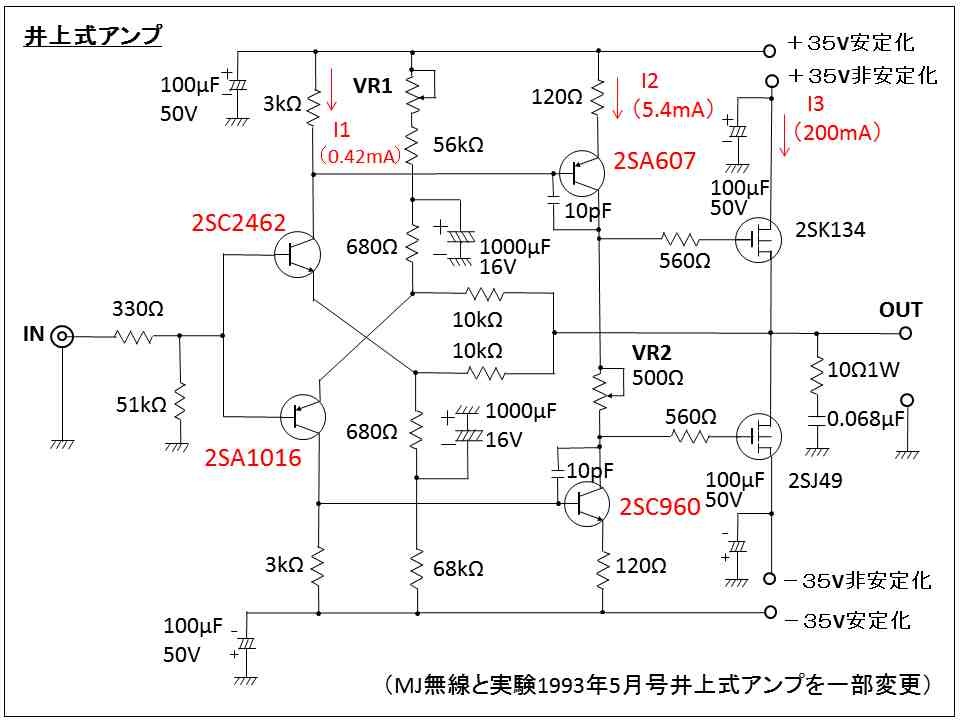
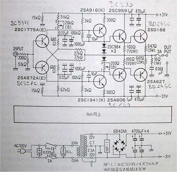
Good good, and biasing modifications similar to those japanese amps... we have a new reference schematics!
Don't forget filtering electrolytes connected to point A and B, I think shaan mentioned about few posts earlier.
Yes don't worry i will try this soon.Good good, and biasing modifications similar to those japanese amps... we have a new reference schematics!
Don't forget filtering electrolytes connected to point A and B, I think shaan mentioned about few posts earlier.
CFH9
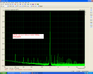
Here is the amplifier as built now.
Here is the amplifier as built now.
Attachments
-
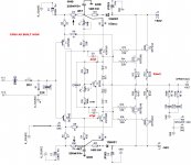 sch cfh9.1 AS BUILT.JPG218.3 KB · Views: 5,321
 -
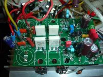 DSC08691.jpg337.5 KB · Views: 526
 -
 2v.PNG107.6 KB · Views: 472
 -
 12V 3WAY.PNG108.3 KB · Views: 440
 -
 90W RMS.PNG110.6 KB · Views: 133
 -
 USING INPUT FILTRR CAPS 220uf.PNG103.5 KB · Views: 136
 -
 32W.PNG69.9 KB · Views: 119
 -
 IMD3.PNG112.2 KB · Views: 110
 -
 IMD2.PNG112.2 KB · Views: 121
 -
 IMD.PNG104 KB · Views: 138
Last edited:
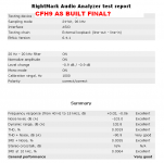
CFH9
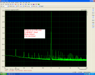
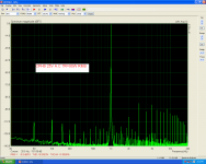
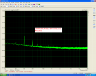
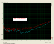
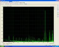
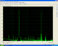
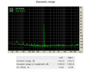
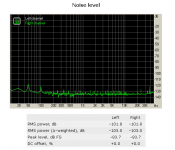
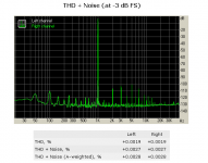
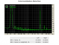
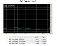
Using RMAA.
Not bad at all for a simple cheap CFA amplifier!
Using RMAA.
Not bad at all for a simple cheap CFA amplifier!
Attachments
Last edited:
- Home
- Amplifiers
- Solid State
- CFH7 Amp