Shaan thanks for the explain.
I don't know if you have read that in the past i had tried to lift this power gnd and leave the gnd for the two input filter capacitors (C14,C16) connected with a separate link to star gnd.
This configuration wasn't good.
See picture
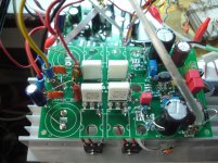
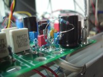
See the power traces from the main filter capacitors to these capacitors. There are(were) two MOSFETs in that trace with no local decoupling. Then a 10R resistor that feeds the capacitors you mentioned and these capacitors feed the input section only. But the VAS is connected to the dirty rail with a 10R with these capacitors having no effect on VAS supply quality. VAS does almost all the voltage amplification and is actually more important in an amplifier than either input stage or output. If VAS supply is compromised then naturally the result could not be good.
")
My thanks goes out to Thimios for being the pathfinder on this amp...
My thanks to thimios too. His uninterrupted passion keeps up the energy of the thread.


See the power traces from the main filter capacitors to these capacitors. There are(were) two MOSFETs in that trace with no local decoupling. Then a 10R resistor that feeds the capacitors you mentioned and these capacitors feed the input section only. But the VAS is connected to the dirty rail with a 10R with these capacitors having no effect on VAS supply quality. VAS does almost all the voltage amplification and is actually more important in an amplifier than either input stage or output. If VAS supply is compromised then naturally the result could not be good.
I agree
No need for cutting,just lift R7,R17, fit a diode and connect the resistors after the diode.So perhaps cut the trace between big caps and Vas caps and out maybe a 10R 1W resistor there to decouple?
The same for R6,R21.
No need for cutting,just lift R7,R17, fit a diode and connect the resistors after the diode.
The same for R6,R21.
This is where a nice picture showing the mod would come in very handy
Yes,wait a little and i will post pictures.This is where a nice picture showing the mod would come in very handy
CFH9
Hi guys,i must say that the problem was the two input filter electrolytics,up to now i didn't have the time to install new parts here so i can't say if this will work.
What i know for sure is that i have even better results.
Up to now it seems that we can save the pcb.
Stay tuned!
Coming soon.
Hi guys,i must say that the problem was the two input filter electrolytics,up to now i didn't have the time to install new parts here so i can't say if this will work.
What i know for sure is that i have even better results.
Up to now it seems that we can save the pcb.
Stay tuned!
Coming soon.
Last edited:
CFH9
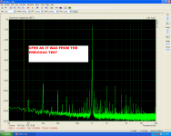
What i have test up to now.
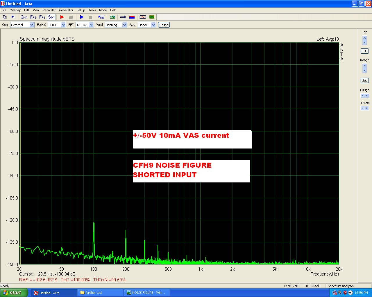
Power supply=+/-50V
VAS current=10mA
Idle current=40mA
Offset=0mV
No zobel!
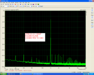
Picture 1 amplifier as it in the previous test.
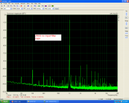
2)Without on board power filter caps.
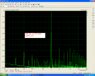
3)Without on board power filter and input filter caps.(please reed the AKK as ALL)
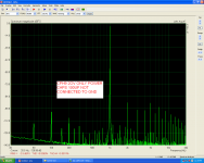
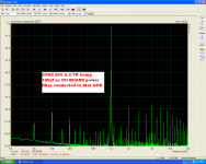
4)Only 100uf on board power filter caps installed and not connected to GND.(50uf rail to rail)
5)Only 100uf on board power filter caps installed and connected to GND.(2V A.C OUT/7R).
6)Only 100uf on board power filter caps installed and connected to GND.(20V A.C/7R OUT).
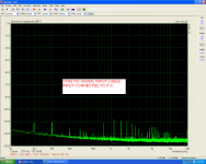
7)Noise figure when amplifier input connected to P.C without signal.
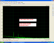
8)Noise figure when amplifier input is shorted.
9)2x100uf INSTEAD OF 4700uf ALL smd 100nf NOT INSTALLED
10)The position where 1N4001 installed.
What i have test up to now.
Power supply=+/-50V
VAS current=10mA
Idle current=40mA
Offset=0mV
No zobel!
Picture 1 amplifier as it in the previous test.
2)Without on board power filter caps.
3)Without on board power filter and input filter caps.(please reed the AKK as ALL)
4)Only 100uf on board power filter caps installed and not connected to GND.(50uf rail to rail)
5)Only 100uf on board power filter caps installed and connected to GND.(2V A.C OUT/7R).
6)Only 100uf on board power filter caps installed and connected to GND.(20V A.C/7R OUT).
7)Noise figure when amplifier input connected to P.C without signal.
8)Noise figure when amplifier input is shorted.
9)2x100uf INSTEAD OF 4700uf ALL smd 100nf NOT INSTALLED
10)The position where 1N4001 installed.
Attachments
-
 start.PNG105.3 KB · Views: 277
 -
 no caps filter.PNG109.9 KB · Views: 264
 -
 ALL CAPS OUT.PNG112 KB · Views: 267
 -
 100UF POWER CAP NOT CON TO GND.PNG113.2 KB · Views: 260
 -
 2 V AC 100UF GND.PNG109.1 KB · Views: 262
 -
 20V 100UF TO GND.PNG111 KB · Views: 98
 -
 NOISE FIGURE.PNG107.3 KB · Views: 85
 -
 NOISE FIGURE WTH A SHORTED.PNG106.4 KB · Views: 471
 -
 DSC08684.jpg337.8 KB · Views: 143
 -
 DSC08683.jpg264.3 KB · Views: 143
Last edited:


Wow. Dang!!!
You are the master detective and pesky B@stard killer!!!

We all eagerly await the final summary of critical changes to make it so. Sounds like big rail filter cap causes problems? Don't understand that as it could as well be big cap from PSU upstream.
One more question: does this mean that the main noise is the 100Hz ripple from PSU so PSRR is -120dB? Then True noise floor without power supply ripple is -150dB??? That's astounding.
You are the master detective and pesky B@stard killer!!!
We all eagerly await the final summary of critical changes to make it so. Sounds like big rail filter cap causes problems? Don't understand that as it could as well be big cap from PSU upstream.
One more question: does this mean that the main noise is the 100Hz ripple from PSU so PSRR is -120dB? Then True noise floor without power supply ripple is -150dB??? That's astounding.
Last edited:
Hooray, the amp is ready to play some Frank Sinatra for Christmas!
Yes, "I'll do it my way!"
I looked over the PCB layout for a little while and thinking "what's up with all the noisy GND buzzing, anyway...", this thread is now so long and difficult to overlook for information on the build and wiring, but I am wondering how GND J4 near OPS, and GND J5 near IPS is wired, do you connect a separate GND wire from each point J4 & J5 to some other GND star point residing at the PSU unit, or do you make as short between J4 & J5 straight across the PCB, and then draw just a single GND wire from either J4 or J5 to the PSU GND point?
I am thinking that if the former is used with dual GND wires, it may cause a GND loop current run around.
I am thinking that if the former is used with dual GND wires, it may cause a GND loop current run around.
Sounds like big rail filter cap causes problems? Don't understand that as it could as well be big cap from PSU upstream.
Could it be that the extra resistance due to wiring between PSU and AMP board mitigates the ringing problem?
Could it be that the extra resistance due to wiring between PSU and AMP board mitigates the ringing problem?
In effect, a CRC filter between the PSU and amp by way of smoothing caps. I suppose one could cut the trace and solder a 0.15ohm
Resistor between the two caps on the amp itself.
- Home
- Amplifiers
- Solid State
- CFH7 Amp