Hmm i can report that never i see this zobel hot,not even warm.Like powering the amp from a very basic PSU and noticing hum level. Removing zobel and checking if the amp is stable without it. Making adjustments to the design or operating condition to improve distortion performance.
But all these are best done by the designer as he would have the best understanding of its behavior.

Hmm i can report that never i see this zobel hot,not even warm.
I have seen amplifiers dancing with a 5MHz 30V oscillation and getting stable instantly as I connect the zobel. This means with the zobel connected the amp won't oscillate as the network kills the oscillation and the zobel doesn't get hot. But the amp must be stable without it because if it is not then there is some problem with the design that is causing the negative feedback to turn into positive which should NOT happen in any audio amplifier. That's why it is wise to test it without zobel make it stable before adding the zobel. Techniques involved are increasing values of Cdom and gate stopper in small steps and stopping at the lowest value that stops the oscillation.
Ok i will try to remove the zobel and test for stability.I have seen amplifiers dancing with a 5MHz 30V oscillation and getting stable instantly as I connect the zobel. This means with the zobel connected the amp won't oscillate as the network kills the oscillation and the zobel doesn't get hot. But the amp must be stable without it because if it is not then there is some problem with the design that is causing the negative feedback to turn into positive which should NOT happen in any audio amplifier. That's why it is wise to test it without zobel make it stable before adding the zobel. Techniques involved are increasing values of Cdom and gate stopper in small steps and stopping at the lowest value that stops the oscillation.
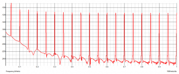
Can you believe that this bad things in low band frequencies have something to do with oscillations?
P.S in any case strange is all these harmonics after the 1KHz basic especially with low level testing conditions(2v A.C).
Last edited:
hi XRK971,
for 2nd GB of CFH9 please add me
- Iancortez 2 PCBs
- Jacques Antoine 2 PCBs
- Zman01 (TBC) 2 PCBs
- schillg11 2PCBs
Best regards
Günni
Hi if not too late I would to order 2 Pcb's too. Thanks for this great Project
- Iancortez 2 PCBs
- Jacques Antoine 2 PCBs
- Zman01 (TBC) 2 PCBs
- schillg11 2PCBs
- cgraf 2 PCBs
regards Christoph
I do not believe the CFH9 is oscillating with the zobel but am a bit concerned about what it would do if the zobel is removed.
It more and more is looking like a PSRR problem.
The input network is quite off the standard value of 1k/10k. With 22K the input stage may have inadequate base drive.
Also the Cdom is 10pF(if I am not wrong) and combined with the low-ish values of 1k/47r it may run into oscillation without zobel. The Cdom's value IMO should be 47-56pF for best stability with the 1k/47r feedback network.
edit: all that said, I don't mean it is a bad design or something. I am only a bit confused from thimios's results.
Last edited:
Practically speaking,i will add some Cdom capacitors parallel to the existing,then i will try to remove the zobel just to be sure,is it necessary to change the input network also like this?I do not believe the CFH9 is oscillating with the zobel but am a bit concerned about what it would do if the zobel is removed.
It more and more is looking like a PSRR problem.
The input network is quite off the standard value of 1k/10k. With 22K the input stage may have inadequate base drive.
Also the Cdom is 10pF(if I am not wrong) and combined with the low-ish values of 1k/47r it may run into oscillation without zobel. The Cdom's value IMO should be 47-56pF for best stability with the 1k/47r feedback network.
edit: all that said, I don't mean it is a bad design or something. I am only a bit confused from thimios's results.
Attachments

Last edited:
Vz,
re post641:
I nearly believed you while I was reading your reply.
But someone nicely put up the sch in post666.
Follow from J3, R17, R11, R3, T1eb, R1 to signal return.
Follow from J2, R21, R10, R2, T2eb, R1 to signal return.
These two currents should be equal. If they are not equal, then there is a net current flow through Rglb (that inappropriate label again) and this gives a DC offset between Signal Return and Decoupling Ground.
If the offset is <<1mV, then we can ignore it.
Last edited:
Vz,
re post641:
I nearly believed you while I was reading your reply.
But someone nicely put up the sch in post666.
Follow from J3, R17, R11, R3, T1eb, R1 to signal return.
Follow from J2, R21, R10, R2, T2eb, R1 to signal return.
These two currents should be equal. If they are not equal, then there is a net current flow through Rglb (that inappropriate label again) and this gives a DC offset between Signal Return and Decoupling Ground.
If the offset is <<1mV, then we can ignore it.
Ah! I see what you mean now. That's right.
Sorry, misunderstanding on my side - I thought by some reason, you meant the positive and the negative inputs of the amplifier and corresponding input currents.
Practically speaking,i will add some Cdom capacitors parallel to the existing,then i will try to remove the zobel just to be sure,is it necessary to change the input network also like this?
As you are willing to experiment I propose the following:
a. Yes make the input network like that.
b. Increase both Cdoms to 47pF.
c. Supply the VAS from input stage supply.
d. Install 1N4007 diodes in series with the 10R that provides input stage power.
e. Try the 2K2/100R config for the feedback network.
f. Reduce VAS current to 10-15mA.
g. If mosfets are connected through wires then install a 100R right to the gate pin of each.
h. This is rare but a faulty capacitor can ruin your day, so if possible replace the electrolytics with another set and see behavior, change one at a time.
CFH9
I i had tried to power input stage and vas from a capacitance multiplier .
Two 47pf added direct on vas transistors( Cdom increasing)
First time vas+inp.
Second time vas only
Third time input only.
No sense!
Then i i had tried to take a measurement with power supply off.
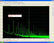
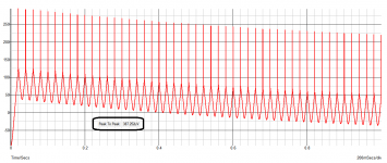
Picture 1 inp. powered from a capacitance multiplier.
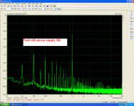
Picture 2 what measured with power supply on.
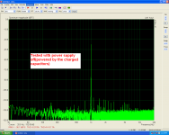
Picture 3 what measured with power supply off(charged capacitors)
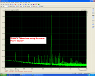
Picture 4 what measured on the Shaan Peeceebee using the same power supply and the same test configuration,to be sure that isn't a power supply problem.
I i had tried to power input stage and vas from a capacitance multiplier .
Two 47pf added direct on vas transistors( Cdom increasing)
First time vas+inp.
Second time vas only
Third time input only.
No sense!
Then i i had tried to take a measurement with power supply off.
Picture 1 inp. powered from a capacitance multiplier.
Picture 2 what measured with power supply on.
Picture 3 what measured with power supply off(charged capacitors)
Picture 4 what measured on the Shaan Peeceebee using the same power supply and the same test configuration,to be sure that isn't a power supply problem.
Attachments
Last edited:
I i had tried to power input stage and vas from a capacitance multiplier .
Two 47pf added direct on vas transistors( Cdom increasing)
First time vas+inp.
Second time vas only
Third time input only.
No sense!
Then i i had tried to take a measurement with power supply off.
Picture 1 inp. powered from a capacitance multiplier.
Picture 2 what measured with power supply on.
Picture 3 what measured with power supply off(charged capacitors)
Picture 4 what measured on the Shaan Peeceebee using the same power supply and the same test configuration,to be sure that isn't a power supply problem.
What happens if you jumper RGLB 10R?
I heard that CFA does not like this kind of floating GND in the input
Regards
It is jumpered already.What happens if you jumper RGLB 10R?
I heard that CFA does not like this kind of floating GND in the input
Regards
I have simulated it in TINA - look back in the thread. The results were very promising which is why we made PCBs.
http://www.diyaudio.com/forums/solid-state/294834-cfh7-amp-16.html#post4802401
http://www.diyaudio.com/forums/solid-state/294834-cfh7-amp-16.html#post4802401
Last edited:
Sorry X i know nothing about simulationI have simulated it in TINA - look back in the thread. The results were very promising which is why we made PCBs.
http://www.diyaudio.com/forums/solid-state/294834-cfh7-amp-16.html#post4802401
Can you play with what Shaan recommended?
Does the simulation say something about PSRR?
I know that simulation isn't a real world test.
Some time ago i have test the Sons of Vhex.The first version wasn't good in PSRR look http://www.diyaudio.com/forums/solid-state/294632-sons-vhex-29.html. I believe that Valery has simulate this also but...the real world show the truth.
In his second version all troubles has gone.look http://www.diyaudio.com/forums/solid-state/294632-sons-vhex-32.html
Last edited:
Inject AC ripple into the rail and see how much gets into the output?
Yes its' easy. Put a 1VPP 50/60Hz sinewave source in series with each power supply. Short the input to ground and trace the output.
I would still try to check what we can see with the oscilloscope, connected to the output, as well as what we see on the rails. Make the input AC-coupled and try to sync what you see at 50Hz. Amplitude is going to be rather low - no problem, just set the sensitivity in a way that we can see the waveform.
I would still try to check what we can see with the oscilloscope, connected to the output, as well as what we see on the rails.
That would be the best thing to do!

The 1X setting on the probe and the scope come in handy here.
- Home
- Amplifiers
- Solid State
- CFH7 Amp