One disadvantage to using this extra resistance in the signal return to decoupling ground connection is that it generates a DC voltage when the +ve current is not exactly matched to the -ve current. That DC voltage error is read by the amplifier stages and becomes an output offset.
Do not unbalance the input stage to cancel this "added resistor" offset. Instead balance the +ve and -ve currents so that the DC voltage across the added resistor becomes <<1mVdc.
Hi Andrew,
Let me clarify one thing. The point with regards to the equal +ve and -ve currents is valid when the input impedances are equal - LTP is a good example.
In case of CFA (like in our case here), +ve input impedance is always mach higher that -ve one (-ve is actually an output) - that's why the feedback network is always very low-impedance. So +ve and -ve currents will never be equal in this kind of CFA arrangement.
This is also a reason why CFAs always have lower PSRR than VFAs (by design). Ripple from the rails is reaching the +ve and -ve inputs at different levels, so it's getting partially eliminated by the common mode signal suppression, but less that it would be cancelled by LTP input stage.
Cheers,
Valery
CFH9
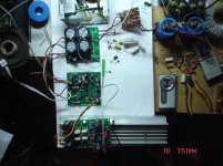
Here is the last test bed.+/-50v
I have to add 3 pictures.
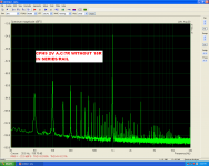
1)testing using +/-50v(5mv ripple)
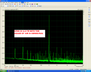
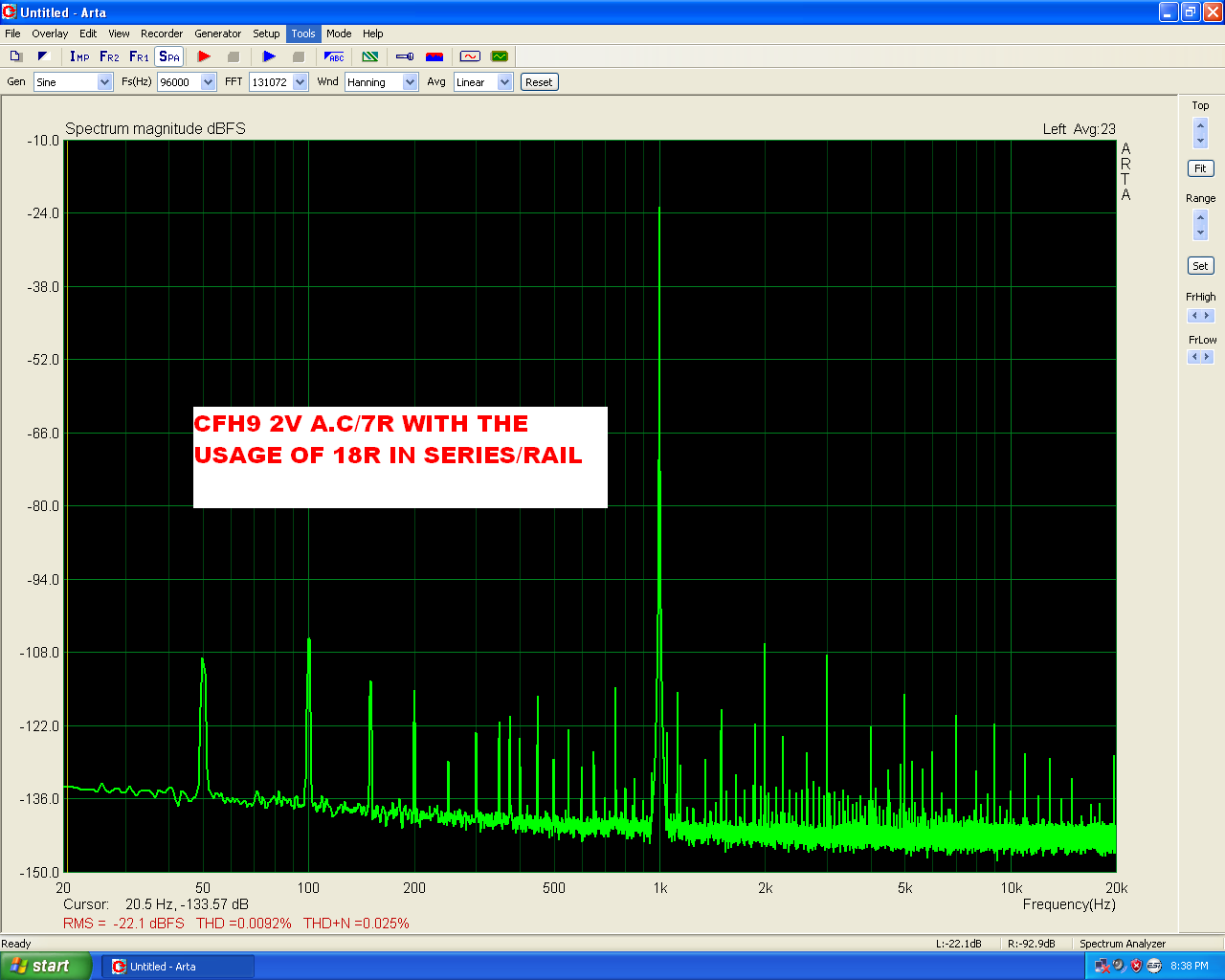
2)the same but using two 18R/RAIL in series.
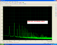
3)what out is, without any inp signal.
Here is the last test bed.+/-50v
I have to add 3 pictures.
1)testing using +/-50v(5mv ripple)
2)the same but using two 18R/RAIL in series.
3)what out is, without any inp signal.
Attachments
Last edited:
He he good questions!Nice setup. I have a few questions.
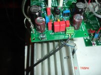
Is the heatsink connected to psu ground?
Does PSU connect to mains earth? If yes then is there any loop breaker between PSU ground and earth?
I have tried all these alternatives but without any success

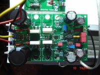
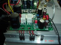
Shaan do you believe that these <<flying>> transistors would be a problem?
Last edited:
Shaan do you believe that these <<flying>> transistors would be a problem?
I was typing exactly this when went back and saw you updated your post.
Answer: they well can be. You know what to do.
Yes i know,just trying to save the moneyI was typing exactly this when went back and saw you updated your post.
Answer: they well can be. You know what to do.
It is a difficult situation here in Greece now.
At least all this will have a good result,a good lesson for pcb designers
.
At least all this will have a good result,a good lesson for pcb designers
Yes for sure, a quite good spirit.....
Marc
It will be useful if someone from guys Marc or X or someone else, having a populated board, can test this without the capacitance multiplier usage.
X said in post#603 that he did notice audible hum as soon as he bypassed the multiplier.
So is the hum a grounding topology issue or is it the circuit and lack of things like CCS etc? I don't recall this problem being present on the CFH7 (no cap multiplier). On that amp I bypassed the ground lift resistor and had a big 12ga solid copper jumper between the two ground circuits.
I wonder if isolating the input ground completely might help?
I wonder if isolating the input ground completely might help?
Thanks Shaan!X said in post#603 that he did notice audible hum as soon as he bypassed the multiplier.
It was something missing from me!
Now i can't believe that the problem have something to do with the <<flying>>transistors.
Yes i know,just trying to save the money
It is a difficult situation here in Greece now.
At least all this will have a good result,a good lesson for pcb designers
Sorry I do not understand what you meant by the first two sentences. I only meant that you may want to mount the transistors directly on board and fasten them all in a heatsink.I do agree these tests definitely will encourage better design. All your tests in different threads do.

So is the hum a grounding topology issue or is it the circuit and lack of things like CCS etc? I don't recall this problem being present on the CFH7 (no cap multiplier). On that amp I bypassed the ground lift resistor and had a big 12ga solid copper jumper between the two ground circuits.
I wonder if isolating the input ground completely might help?
Looks like a lot of worst-case tests need to be done on CFH9.
Don't worry Shaan i didn't misunderstand
I do agree these tests definitely will encourage better design. All your tests in different threads do.
Please say detailsLooks like a lot of worst-case tests need to be done on CFH9.
Thanks Shaan!
It was something missing from me!
Now i can't believe that the problem have something to do with the <<flying>>transistors.
Long leads on transistors cannot be helping the situation. I will check if putting a jumper between two ground circuits helps. It has something to do with layout topology and that extra ground system for the inputs.
But as I said, with the cap multiplier it's not an issue. The additional MOSFET and two caps is a cheap trivial solution with lots of benefits beyond hum reduction.
So is the hum a grounding topology issue or is it the circuit and lack of things like CCS etc? I don't recall this problem being present on the CFH7 (no cap multiplier). On that amp I bypassed the ground lift resistor and had a big 12ga solid copper jumper between the two ground circuits.
I wonder if isolating the input ground completely might help?
X, The rearrangement in the signal gnd make the results better as you can see on the graphs where output traced without any input. signal,but can't solve the problem.
In all the CFA topology PSRR is low and a little hum is present but in your amplifier something is strange.I will try to find a better solution for the heatsink and i will report again
i did the same for my Jason VSSA build and it worked fine...Jumper the ground lift, as Shaan already recommended
Please say details
Like powering the amp from a very basic PSU and noticing hum level. Removing zobel and checking if the amp is stable without it. Making adjustments to the design or operating condition to improve distortion performance.
But all these are best done by the designer as he would have the best understanding of its behavior.
edit:
Will wait for thimios' next tests.I will try to find a better solution for the heatsink and i will report again...
Last edited:
- Home
- Amplifiers
- Solid State
- CFH7 Amp