Hi,
I think you've done a superb job of that pcb, very compact and nice layout. It has given me some further food-for-thought. I also like your choice of output devices. I do have a bag of BJTs to use up but Lateral's have such a good reputation these days...
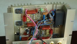
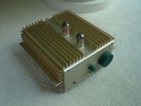
Thanks Bigun. The amp sounds pretty good and it is small.
This one is made from parts mainly from Active Surplus on Queen st. To. ,about 10 years ago. I believe the extrusions was for car power amps, I used two off for the amp.
Attachments
Member
Joined 2009
Paid Member
Member
Joined 2009
Paid Member
My thinking on this project has evolved again.
I have a chasis with 2N3055 BJTs on heatsinks, a 240VA power trafo with two 18V AC secondary windings. The original plan for this chasis was a JLH 10W 1969 version. I will likely still make that. But I don't see why the same chasis can't be used to allow me to play with a 2nd hybrid design - thus resurecting this thread.
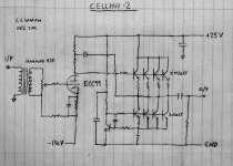
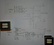
I want to keep it real simple. A powerful triode directly driving the output BJT's with their base current and providing voltage gain. No gnf. My thoughts turn to the ECC99 (since I have a couple of them).
Thoughts on the attached schematic ?
I have a chasis with 2N3055 BJTs on heatsinks, a 240VA power trafo with two 18V AC secondary windings. The original plan for this chasis was a JLH 10W 1969 version. I will likely still make that. But I don't see why the same chasis can't be used to allow me to play with a 2nd hybrid design - thus resurecting this thread.
I want to keep it real simple. A powerful triode directly driving the output BJT's with their base current and providing voltage gain. No gnf. My thoughts turn to the ECC99 (since I have a couple of them).
Thoughts on the attached schematic ?
Attachments
I'm wondering if a pair of voltage doublers would be better - being symmetrical about the GND their ripple would be similar but opposite and afford better psrr ? And from a safety perspective I don't have such a high voltage wrt to gnd - just have to be careful not to get myself across the + and -.
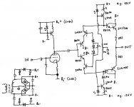
I've thought about what devices I have on hand too and have picked out some transistors - I've updated the schematic to show them.
I'm also toying with the idea of using Nuvistors for the tube.
Hi guys!

Is this schematics work?
Is someone made this amplifier for this schematic?

Please give values (codes) components of the schematic.
thank you!
Attachments
Last edited:
Member
Joined 2009
Paid Member
Hi Gost22, I don't think this has been built yet. The individual pieces have been built - meaning that the input stage is a common-cathode voltage amplifier with current source anode load has been built many times by people. The parts values are easy to work out if you know which valve/tube you want to use. The output stage is the KRILL amplifier which has been built many times and there's a thread about it on this forum with all the parts values etc.
Member
Joined 2009
Paid Member
- Status
- This old topic is closed. If you want to reopen this topic, contact a moderator using the "Report Post" button.
- Home
- Amplifiers
- Tubes / Valves
- CELLINI-2 a hybrid