Member
Joined 2009
Paid Member
Well Broskie is a bit of genius with tubes but his blog isn't necessarily a starting point for a beginner. The key thing is that we want voltage amplification with high input impedance and the common cathode single-triode amplifier stage I've proposed does this quite well. The output impedance is dependent on the tube and how the plate (anode) is loaded but I feel there's a fair number of choices of tubes that will work because this diamond buffer has a high input impedance.
I also prefer a simple single ended triode for the voltage amplifier, it produces the 'classic' harmonic structure dominated by 2nd harmonic which will help with the overall distortion profile of the amplifier given that the SS output is symmetrical and so will have dominant odd order harmonics.
I'd be interested to see your pcb design.
Psu suggestion
Hi,
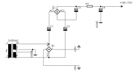
Here is my suggestion for the PSU. low voltage rails are for the buffer and High voltage rail is for the triode gain stage.
The dc offset of the VGS can cause trouble but maybe a servo could be the answer for that. Stuart Yaniger shows a nice circuit in his website.
Jarno
Hi,
Here is my suggestion for the PSU. low voltage rails are for the buffer and High voltage rail is for the triode gain stage.
The dc offset of the VGS can cause trouble but maybe a servo could be the answer for that. Stuart Yaniger shows a nice circuit in his website.
Jarno
Attachments
Member
Joined 2009
Paid Member
I'm wondering if a pair of voltage doublers would be better - being symmetrical about the GND their ripple would be similar but opposite and afford better psrr ? And from a safety perspective I don't have such a high voltage wrt to gnd - just have to be careful not to get myself across the + and -.
I've thought about what devices I have on hand too and have picked out some transistors - I've updated the schematic to show them.
I'm also toying with the idea of using Nuvistors for the tube.
I've thought about what devices I have on hand too and have picked out some transistors - I've updated the schematic to show them.
I'm also toying with the idea of using Nuvistors for the tube.
Attachments
You're using CCS load so I don't think this is a good idea. You're injecting PSU noise into cathode. This noise wouldn't be there if you used multi-stage single-side B+ multiplier (if needed in the first place) instead. CCS provides all the PSRR you need as long as your "B2+" supply can provide the current required.
Member
Joined 2009
Paid Member
Good point, with CCS load I don't have symmetrical power supply ripple at the front end.
With single sided voltage boosting is there a reason to choose to boost the B+ rather than the B- or is it a matter of convention ?
My thinking about providing additional voltage is to increase my choice of tubes.
With single sided voltage boosting is there a reason to choose to boost the B+ rather than the B- or is it a matter of convention ?
My thinking about providing additional voltage is to increase my choice of tubes.
Hello,
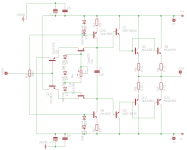
Here is my OPS schematic. I just made pcb for it and mounted the components.
Works ok but I have trouble with dc-offset. When I short the input to ground with 1k resistor the offset is about 250mV at the output in both channels.
My rails are at +-50V.
During the next weekend I am planning to try the VGS. It is based on the gain stage presented in SY:s article "His Masters Noise".
I am still thinking about the dc servo for the output stage. Steven Dunlap presented a little complicated servo system with ldr:s but I am looking for something easier if possible.
Attachments
Member
Joined 2009
Paid Member
Hi Jarkaa,
I guess the dc-offset is a function of how well the input devices are matched for beta.
I was wondering if you found any differences in sound with the following changes:
Did you find C1 to be necessary ?
What idle current do you use through the input devices ?
What idle current do you use through the output devices ?
Member
Joined 2009
Paid Member
The Krill thread is very long and I don't have the patience to find the one single reference to C1 - but I suspect you can disconnect it without any disadvantages at all.
What I mean by input current is not the input impedance by the way but how much current flows through the input devices. I believe it makes a very big difference to the distortion level of the output - 1mA would be too little, 10ma would be good. I wondered if you had experimented with it. I guess I can try it out when I build mine
What I mean by input current is not the input impedance by the way but how much current flows through the input devices. I believe it makes a very big difference to the distortion level of the output - 1mA would be too little, 10ma would be good. I wondered if you had experimented with it. I guess I can try it out when I build mine
Hello,
Here is something about the c1
http://www.diyaudio.com/forums/solid-state/134619-krill-little-amp-might-109.html#post1765381
Based on AKSA:s post I would´n remove the c1 cap.
Here is something about the c1
http://www.diyaudio.com/forums/solid-state/134619-krill-little-amp-might-109.html#post1765381
Based on AKSA:s post I would´n remove the c1 cap.
Member
Joined 2009
Paid Member
Sure,
I have the amplifier up and running.
Front end is ccs loaded plate follower with maida regulated PSU, cathodes are biased with red leds.
Ccs is set to 10mA and the maida is fed from the voltage multiplier in the main power supply.
Heaters are powered from a separate 6.4vac tranny.
I can upload few images of the prototype when I get home.
The power follower is basically Krill´s outputstage with adjustable current sources. Rails are at +-50v
At first I had some trouble with dc offset at the output but now everything works fine.
I really can´t comment on the sound yet because my main speakers are in the "process" right now but the amp is completely hum free and stable.
I will make a new pcb for the power follower modules and for the triode stage when I have more time. Now the vgs is hardwired on and a piece of old pertinax board.
Jarno
Member
Joined 2009
Paid Member
Fantastic !!!! - I'd love to see some photos. The real thing is some listening impressions particularly at low volume and then at higher volume - when you get the chance...
what idle current though the output devices did you settle on - or is this to be decided only after listening tests ?
what idle current though the output devices did you settle on - or is this to be decided only after listening tests ?
Member
Joined 2009
Paid Member
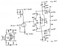
So I have done some initial experiments - starting with listening to a very basic class AB triple emitter follower - see diagram...
It's not a very nice tube, Chinese 6N1, but the tube socket is wired up for this tube and the pin-out isn't compatible with any other tubes I have on hand.
Interesting to listen to this thing compared with my all-tube Cellini (the original) amplifier and my all-transistor TGM3 amplifier. Listening levels at 1W.
Bass: deeper and fuller with Cellini, thinner but more articulate with TGM3, the hybrid bass is also thinner and more articulate.
Mids: mellow and rich with Cellini, thinner and more open with TGM3, the hybrid is somewhere between the two, being not as rich as Cellini but richer than TGM3 and yet also more open like TGM3 - a nice tone.
Highs: mellow, smoooooth but a bit rolled-off with Cellini, clear, open and a bit grainy with TGM3, the hybrid retains the smoothness of Cellini but has more clarity and extension.
I'm encouraged by the results of the hybrid, I detect some real promise here, but it still lacks something, the sound of the Cellini has more content somehow [I suspect the hybrid's tube as being a weak link]. What I'd like is the smooth extended high's of the hybrid, the dynamics of the TGM3 and the rich tones of the Cellini.
At higher powers the Cellini amp runs out of steam and is left behind. TGM3 retains it's sound, becoming even more dynamic. The hybrid struggles, it doesn't sound dynamic and loses it's composure. I suspect the difference here lies in the lack of gnf around the triple EF, which must be generating a lot more distortion as the signal increases.
I think distortion and output impedance of the hybrid needs to be improved and I can think of two approaches - some negative feedback, or multiple paralleled output devices. It may also benefit from a different topology than the triple EF.
Attachments
Last edited:
Currently I working on a same hybrid amplifier. Single E88CC VAS stage+triple EF. But there is lot of possibilities to make some fine tuning the solid state part.
I want to avoid the feedback, only the tube stage has some local feedback, due the cathode resistor.
I use Toshiba predriver, and driver, and Onsemi outputs. You should try to keep the input impedance of the followers as high as possible.
Sajti
I want to avoid the feedback, only the tube stage has some local feedback, due the cathode resistor.
I use Toshiba predriver, and driver, and Onsemi outputs. You should try to keep the input impedance of the followers as high as possible.
Sajti
Member
Joined 2009
Paid Member
Currently I working on a same hybrid amplifier. Single E88CC VAS stage+triple EF. But there is lot of possibilities to make some fine tuning the solid state part.
good to hear others are out there doing these experiments too, what possibilities do you considering in tuning of the SS part if not simply adding output pairs ?
I want to avoid the feedback, only the tube stage has some local feedback, due the cathode resistor.
I am all in favour of avoiding feedback because it's complex to do with good results and because it has some detrimental impact on harmonic profile. But in this case I am wondering if this is false thinking - you see I am not running this output in Class A, but Class AB so I have cross-over and gm doubling artifacts. I also have 100% local feedback because the output is a Follower. So I already have high orders of harmonic distortion and can't avoid it being there - so I may as well use nfb as a tool to reduce it ????
I am actually thinking of two projects, one can't handle the heat dissipation from a Class A output design, the other can. With Class A I believe it's 'easier' so I'm tackling the more difficult case of Class AB first.
good to hear others are out there doing these experiments too, what possibilities do you considering in tuning of the SS part if not simply adding output pairs ?
Try different bias settings, for predrivers nad drivers. Try different types, as well.
I am all in favour of avoiding feedback because it's complex to do with good results and because it has some detrimental impact on harmonic profile. But in this case I am wondering if this is false thinking - you see I am not running this output in Class A, but Class AB so I have cross-over and gm doubling artifacts. I also have 100% local feedback because the output is a Follower. So I already have high orders of harmonic distortion and can't avoid it being there - so I may as well use nfb as a tool to reduce it ????
Crossover distortion is OK. But You have no gm doubling problem, because the input impedance of the triple is very high comparing to the anode resistor of the tube stage. My triple EF has the input impedance about 54kohm with 8ohm load, and 53.2kohm with 2ohm loas. The bias setting resistors are 110kohms, which means 55kohm input impedance with no load.
My simulation shows mainly 2nd, 3rd harmonic. Every other is minimum 20dB down, some of them 40dB lower. The bias over 50mA/output pair, makes no significant difference in distortion.
I use 4output pairs with +/-65V rails.
Sajti
Member
Joined 2009
Paid Member
So, you are saying that the gm doubling is an issue only because it represents a non-linear load on the stage that is driving it and so long as we have a triple there is enough current gain to shield the tube from this effect ?
4 output pairs - no wonder you are happy, my simulations showed a significant improvement in output impedance and distortion levels when you increase from one pair to two pairs and no doubt further gains as the number of pairs increases further. But one of my projects is a multi-channel amp and I don't need high power - buying and matching multiple output pairs seems undesirable in terms of cost and power dissipation - at some point it becomes viable to use an all-tube solution. I'm wondering if I have to match the pairs at all, since I don't need full power I don't worry about current hogging since my application will keep a single output pair within their SOA ??
Edit: I have now discovered I have been listening to a double EF not a triple EF. This explains why it fell apart at higher volume!
Last edited:
So, you are saying that the gm doubling is an issue only because it represents a non-linear load on the stage that is driving it and so long as we have a triple there is enough current gain to shield the tube from this effect ?
Gm doubling is not issue if You have heavier linear load on the VAS stage, than the EF.
4 output pairs - no wonder you are happy, my simulations showed a significant improvement in output impedance and distortion levels when you increase from one pair to two pairs and no doubt further gains as the number of pairs increases further. But one of my projects is a multi-channel amp and I don't need high power - buying and matching multiple output pairs seems undesirable in terms of cost and power dissipation - at some point it becomes viable to use an all-tube solution. I'm wondering if I have to match the pairs at all, since I don't need full power I don't worry about current hogging since my application will keep a single output pair within their SOA ??
I need four pairs because of the high output power (400W/4ohm). I use NJW0xxx output devices they are quite linear up to 3A. You don't really need to order lot of them to find pairs. But if You use only 8ohm load, then single pair should be enough.
I made lot of listening, with different types, and bias (such as driver bias between 5 and 100mA) and after this sessions I put together the prototype.
Sajti
- Status
- This old topic is closed. If you want to reopen this topic, contact a moderator using the "Report Post" button.
- Home
- Amplifiers
- Tubes / Valves
- CELLINI-2 a hybrid