Member
Joined 2009
Paid Member
I need four pairs because of the high output power (400W/4ohm). I use NJW0xxx output devices they are quite linear up to 3A. You don't really need to order lot of them to find pairs. But if You use only 8ohm load, then single pair should be enough.
I made lot of listening, with different types, and bias (such as driver bias between 5 and 100mA) and after this sessions I put together the prototype.
Sajti
I don't think it's so simple. Your output devices are not linear at any current, they are bipolar transistors and the current flow through them is an exponential function of the voltage between base and emitter. It's only the large negative feedback that occurs on an emitter follower configuration that gives any hope of linearity for this output. Even then, the more current that flows through the device, the larger the voltage between base and emitter and the less linear the device is. By having more devices in parallel each device now only deals with a smaller current and as a result the voltage between base and emitter is smaller and the distortion is less. More output pairs = less distortion to first order.
Member
Joined 2009
Paid Member
Well I have been reading a lot more on the internet - there's so much to learn from everyone who has trodden this path before me I no longer feel the need to do any design work - just sift carefully through all of your advice, then build and listen !!!!! it's like a weight just got lifted off my shoulders 
If You apply the BJT as EF, you need linear current gain. If you push in 1mA into the base, you want -say- 100mA from the emitter. If you poush 2mA, you need 200mA. And this devices do it very well, up to 3A current.
My experience is the transistor sound resulted by the nonlinear capacitances of the ss devices. So I choose the transistors, woth the lowest internal capacitances. This gives very smooth highs.
Sajti
My experience is the transistor sound resulted by the nonlinear capacitances of the ss devices. So I choose the transistors, woth the lowest internal capacitances. This gives very smooth highs.
Sajti
Member
Joined 2009
Paid Member
Hey! that's pretty good - open loop I assume. How did the harmonics look in your simulation - not too much nasty H5, H7 ?
Almost clean 3rd harmonic. Every other is minimum 20dB down.
Sajti
Member
Joined 2009
Paid Member
hmmm, I don't know if I want 0.25% of H3 - I assume it's clean sounding but 'solid state' sounding too ?
If You apply MJL21193/94 output devices, You have about 0.5% of distortion both 2nd, and 3rd harmonic on same level...
Sajti
hmmm, I don't know if I want 0.25% of H3 - I assume it's clean sounding but 'solid state' sounding too ?
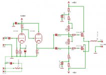
OK, I just finished your amplifier. With feedback, tube driver. It gives 50W/8ohm, with 0,1%.
2nd harmonic:0.096%
3rd 0.025%
4th:0.0023%
5th:0.0062%
Every other is lower.
Sajti
Member
Joined 2009
Paid Member
That looks pretty good, so you decided to try with feedback - how does it sound with and without ?
Can I order this amplifier for delivery from you
I will have to get into my basement this weekend and start working on some prototyping again, you are making me feel guilty and lazy but also encouraging me !
Can I order this amplifier for delivery from you
I will have to get into my basement this weekend and start working on some prototyping again, you are making me feel guilty and lazy but also encouraging me !
It was just a simulation. So I can't tell You anything about the sound of it. My experience, that the non feedback version sounds better. THD is not a really big issue.
But after some more adjustment I can push down the distortion even lower. About 0.05%.
I can attach the schematic tomorrow.
Sajti
But after some more adjustment I can push down the distortion even lower. About 0.05%.
I can attach the schematic tomorrow.
Sajti
Last edited:
Member
Joined 2009
Paid Member
I'll take that input and resolve not to use gnf in the design.
I have also decided that it must operation in Class A over a useful region of power output - since this is DIY I need not accept the compromise that comes with the more common Class AB operation. For my applications I don't think I need more than a few W of power in Class A. In order to allow for a reasonable transition to Class B so that the amplifier can better handle occasional large-transients it makes sense to stick with a Push-Pull design that can handle at 5x to 10x the limit of the Class A region.
So the candidates which have only local degenerative feedback are:
a) three stage: the triple EF using BJTs
b) three stage: based on diamond buffer
c) two stage: BJT driving MOSFET
d) two stage: JFET driving MOSFET (a.k.a. Nelson's F4)
On first inspection two stages has the added attracting of fewer active devices in the signal chain, although I've never used MOSFETs before.
Member
Joined 2009
Paid Member
I found that Digikey has NJW0281 but is a non-stock item. However, when I look at the data sheet it has Cob = 400pF, but the 5200 parts I have data sheet says Cob = 200pF and also very stable Hfe up to 3A. I think the 5200 looks better, on paper at least.
e) yes, the cathode follower would be a buffer to allow only two stage EF. This is a good idea, but I have two projects, a 6 channel version and a 2 channel version and first I will focus on the 6 channel version where more compromises are allowed. For this many channels I prefer only one tube and I have already some single triodes for this. So maybe I will stick with triple EF.
f) did you see this design from Renardson ? http://www.angelfire.com/ab3/mjramp/pagefour.html
It has a CFP structure, I don't want to use this kind of built-in nfb in the 2ch project but for 6-ch project maybe it's worth a gamble. It's a triple BJT output, look at figure 5. I simulated this, a fully complimentary/symmetrical version and it pulls the harmonics lower as promised.
I'm thinking about how best to achieve a good transition from Class A into Class B. And it seems one option is to use three output pairs with low value emitter resistors I can bias them optimally for Class AB and get the first 1W - 2W in Class A. I'm not looking for more Class A for the 6 channel version. The idea comes from here: http://www.diyaudio.com/forums/solid-state/111756-rmi-fc100-single-stage-audio-power-amplifier.html
Last edited:
Mouser has them. It's quite cheap.
If You check the capacity, please note the 2SC5200 has 200pF typical, and the NJW has 400pF maximum. Typically it's 150pF.
The tuibe cathode follower makes the music more dynamical. I never heard the ARC HD220 (but I hope I will on the next week), which use 6H30 cathode follower to drive the EF output stage, but I heard c-j ET250S, which use single E88CC with paralleled sections. The c-j sounds good, but as I read the ARC has more "power" even with lower output power.
But for 6 channel the 6H30 looks quite cheap.
I tried CFP output for tube VAS, and it sound strange for me. Few years after my listening, I read that the CFP has nonlinear input impedance, what can be problem with the tube.
Currently I'm thinking to build something like Marantz MA9 output buffer, which is feedbacked power amplifier, with voltage gain of 2.5. This can ideal to drive with tube. It has low distortion (0.002%), so the THD coming from the tube VAS, will depend the final sound quality, if I'm right.
I set the bias to 50-100mA depending the Re. I usually apply 0.22ohms, and set some 75mA. This looks OK for me.
Sajti
Member
Joined 2009
Paid Member
NJW/5200 - well I was quite wrong then, but fortunately learned of a good transistor ! Final choice maybe influenced by fact that I have some 5200's to use up but this depends on whether I have to critically match them - with larger emitter resistors I may not have to.
OK, so advice is to avoid CFP - but there is a big difference between CFP in Class AB and in Class A - did you listen in Class A or not ? I know that CFP is horrible if you let is operate in Class B.
But I also remember reading from D. Self that the CFP is not as low distortion as EF at very low signal levels - it's usually understood that it's better at high signal levels but few people look at the very low signal levels. I think it would be a Copyright violation to post the data here but if you search online for his book...
I never heard of this Marantz design, do you have a schematic you can post/share ?
Member
Joined 2009
Paid Member
Regarding cathode follower. If I am to provide for additional tubes I would need to see a significant benefit since it's additional heater power and B+ power. The 6C52H has a 130mA heater at 6.3V, runs off 120V plate voltage and is tiny so it's not hard to accommodate it.
I could sacrifice some more of the same triode. In CF configuration the output impedance is around 1/gm which is around 100 Ohm, pretty darn good for a tube - maybe I got this calculation wrong.
Question is - is it worth another tube, CF doesn't allow the tube to add much of it's character so maybe BJT is a better choice and just as linear if set up properly ?
I never heard of this Marantz design, do you have a schematic you can post/share ?
You can get the service manual of the MA9S1 from here:
MARANTZ MA-9S2 Service Manual free download, schematics, eeprom, repair info for electronics
My design are based on the power buffer of it. I use no bridged output, and I made some changes, but the main concept is same.
Sajti
Regarding cathode follower. If I am to provide for additional tubes I would need to see a significant benefit since it's additional heater power and B+ power. The 6C52H has a 130mA heater at 6.3V, runs off 120V plate voltage and is tiny so it's not hard to accommodate it.
I could sacrifice some more of the same triode. In CF configuration the output impedance is around 1/gm which is around 100 Ohm, pretty darn good for a tube - maybe I got this calculation wrong.
Question is - is it worth another tube, CF doesn't allow the tube to add much of it's character so maybe BJT is a better choice and just as linear if set up properly ?
I have a couple of PCB-s for a simple hybrid ECC88/MosFet amp, if you are interested I can send it to you.
You could use it for starters , possibly the tube part, also maybe with different component values.
Attachments
Member
Joined 2009
Paid Member
- Status
- This old topic is closed. If you want to reopen this topic, contact a moderator using the "Report Post" button.
- Home
- Amplifiers
- Tubes / Valves
- CELLINI-2 a hybrid