When you say it doesn't regulate, is the output voltage zero, maximum or some intermediate value?
The output maxes out to the MOSFET's drain voltage.
I suppose you're aware that LM358 and LT1077 have a different pin-out, but let's not leave any turn unstoned....
I'm aware
 , but it's good to address every option.
I'll try to breadboard it myself ASAP, but in the mean time, you can measure the voltages at every node wrt GND and write them on the schematic, this should help to trace the origin of the problem
I'll do that, although I am a bit weary of leaving it on, not knowing what's going wrong.
One other thing I noticed with the LT1077 in place, is the output starts to oscillate at around 250mA (350mA with a 0.5ohm current sensing resistor). I know the breadboard doesn't help, but I think it could be more stable. I'm trying to track where the oscillations are coming from, sbut no luck so far. Just a heads up.

Last edited:
You can leave it on, there is no risk whatsoever: all the control electronics is tied to the high side, with resistors as the only path to the negativeI'll do that, although I am a bit weary of leaving it on, not knowing what's going wrong.
The approximate frequency of oscillation could give valuable clues: if it highish, MHz or more, it likely to be caused by the wiring, especially the gate and source of the MOS. If it is lower, tens of KHz or thereabout, it would rather be caused by closed loop stability problems. In this case, you can try to overcompensate the opamp, use 1nF instead of 220pF, and short the series resistor.One other thing I noticed with the LT1077 in place, is the output starts to oscillate at around 250mA (350mA with a 0.5ohm current sensing resistor). I know the breadboard doesn't help, but I think it could be more stable.
Yes, for breadboarding that is certainly a good advice. I have omitted it on the schematic, because the impedances of the circuit are such that it is normally not needed with a PCB or veroboard construction, but with flying leads on the gate and/or source, it is probably required.Perhaps a 1k resistor between gate and the rest of the circuit will help,resistance close to the fet.
1K might be a bit much though: it could create a parasitic pole and begin to interfere with the main compensation. 100 ohm to begin with seems reasonable; if it has a huge effect, it is worth investigating further and trying other values, otherwise the problem probably has another origin
Update, oscillations fixed:
A gate stopper did little to no good. Started with a 220ohm without result. A 1k stopper even made the whole thing oscillate like crazy! The frequency of the oscillations were around 66k, so like Elvee advised, the feedback loop was next. I now have a 1n ceramic cap without the series resistor in place and all is well. I can get it to an average of 525mA (as high as it needs to go) without any problems. I now can experiment to determine optimum values. I'll also have another look at R6 as Ketje suggested.
Any input is welcome.
Edit: without a gate stopper entirely, load regulation is better as might be expected
Edit2: I reverted back to the 220pF cap, still without the series resistor. still no oscillations (at 300Hz to 3kHz).
Last edited:
It is a good thing to have solved this issue; I will look more seriously into the loop stability conundrum, as soon as I have some time (normally Tuesday next week).Update, oscillations fixed:
So far, I didn't make a proper loop analysis, just square wave tests, but they are normally revealing enough, especially when native LTspice models are used, which is the case here with the LT1077.
Since the 1K stopper made things worse, I would think the problem comes from the MOS input capacitance you use, compared to the STP8NM60 I used for the sim.
Anyway, a frequency of 66KHz is typical of a global loop stability problem.
It is a good thing to have solved this issue; I will look more seriously into the loop stability conundrum, as soon as I have some time (normally Tuesday next week).
So far, I didn't make a proper loop analysis, just square wave tests, but they are normally revealing enough, especially when native LTspice models are used, which is the case here with the LT1077.
Since the 1K stopper made things worse, I would think the problem comes from the MOS input capacitance you use, compared to the STP8NM60 I used for the sim.
Anyway, a frequency of 66KHz is typical of a global loop stability problem.
Yes, the IRFBC40s input capacitance is 1300pF. Way higher than the STP8NM60. I look forward to your findings and will keep posting my findings in this thread.
Shunting the zener with a 22nF could solve the problem without overcompensation then, but one has to be careful with this kind of solution: it will make the MOS much more prone to oscillation, and the output of the opamp could also be destabilized.Yes, the IRFBC40s input capacitance is 1300pF. Way higher than the STP8NM60. I look forward to your findings and will keep posting my findings in this thread.
Your measurements on the 358 version will certainly shed some light on the problem. As an afterthought, it would be better to reference them to - supply of the opamp (or the output if it is more convenient). The resolution will be better
You mean the zener going to the base of the BC557 I presume?
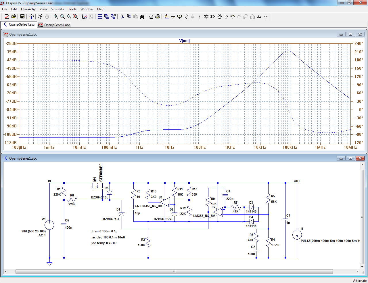
I did some simulations with the IRFBC40 (found a proper model). It shows a high spot at 137kHz of -13.8dB. Way higher than the STP8NM60. I recon it's due to the higher capacitance. This could be an issue for a bigger poweramp I have in my mind. MOSFETs with higher power ratings and voltage handling tend to have higher capacitances. Ive seen up to 3100pF. It's still not really clear to me how to properly compensate a loop like this one.
I can alter the values in the opamp's feedback loop to 1k ohm and 1nF, getting the high spot down to -20dB, but it doesn't seem right, as you pointed out it's overcompensating.
YesYou mean the zener going to the base of the BC557 I presume?
The characteristics of the MOS can be designed in an adapted circuit, without watering down of any performance.I did some simulations with the IRFBC40 (found a proper model). It shows a high spot at 137kHz of -13.8dB. Way higher than the STP8NM60. I recon it's due to the higher capacitance. This could be an issue for a bigger poweramp I have in my mind. MOSFETs with higher power ratings and voltage handling tend to have higher capacitances. Ive seen up to 3100pF. It's still not really clear to me how to properly compensate a loop like this one.
I can alter the values in the opamp's feedback loop to 1k ohm and 1nF, getting the high spot down to -20dB, but it doesn't seem right, as you pointed out it's overcompensating.
When you overcompensate, you buy yourself tranquility, but at the expense of performance.
Of course, that is always better than an oscillating supply, but ideally it should be stable without any downgrading. And it has to be possible
I've done some measurements on the LM358 circuit, as I really wanted it to work (a lot cheaper opamp! ). Although the + input was 0.4V lower than the -input, the output remained (almost) 0V. So the opamp itself became suspect. I had previously already replaced it with another LM358 but it gave the same result. Not knowing what else it could be, I popped in a third and PSU regulated as it did with LT1077. So I don't know if the LM358 is way more sensitive to static discharges, TI provided me with some bad ones, just bad luck, or some kind of start-up protection needs to be added, but the circuit works properly with this different opamp.
Another added bones: there are no oscillations under full load with the original component values. Seems the LT1077 is more sensitive.
). Although the + input was 0.4V lower than the -input, the output remained (almost) 0V. So the opamp itself became suspect. I had previously already replaced it with another LM358 but it gave the same result. Not knowing what else it could be, I popped in a third and PSU regulated as it did with LT1077. So I don't know if the LM358 is way more sensitive to static discharges, TI provided me with some bad ones, just bad luck, or some kind of start-up protection needs to be added, but the circuit works properly with this different opamp.Another added bones: there are no oscillations under full load with the original component values. Seems the LT1077 is more sensitive.
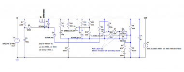
I have breadborded it (this version: http://www.diyaudio.com/forums/atta...s-zeners-resistors-450v-reference-hvsupp5.png ) with a rather uninteresting result: it simply worked as expected (LM358 from NS, not yet TI).I've done some measurements on the LM358 circuit, as I really wanted it to work (a lot cheaper opamp!
I then tried to induce a latch-up and bingo! Instead of starting normally the input voltage, I first started the input supply with the regulator disconnected, and then only I made the connection. This results in the input voltage going from 0 to 500V in a µs or so, and it did trigger the latch-up.
After inspection, I thought the most likely cause was the voltage divider pulling too much current from the + output, and stealing the tail current from the PNP input causing a phase reversal.
I tested the theory by replacing the protection 1N4148 by BAT85, and the latch-up was gone.
I also tried an alternative solution, inserting a 22K resistor directly in the + input after the 1N4148's, and it also worked
Attachments
I've altered my breadboard to your last schematic as well, but am again faced with osculations. 20Vpp @ 41kHz. Funny thing was, I forgot to take out the BC557 at first try and everything worked well (although load regulation seemed worse). Once I took the BC557 out, oscillations began. Could this be due to the MOS I'm using and the BC557 helping to stabilize things?
Edit: This time a 1k gate stopper did reduce the osculations, but at +/- 300mA load, oscillations start again
Edit: This time a 1k gate stopper did reduce the osculations, but at +/- 300mA load, oscillations start again
Last edited:
Yes that is very likely: the larger input capacitance of the MOS is driven by the low impedance of the emitter follower, and this pushes the parasitic pole higher.I've altered my breadboard to your last schematic as well, but am again faced with osculations. 20Vpp @ 41kHz. Funny thing was, I forgot to take out the BC557 at first try and everything worked well (although load regulation seemed worse). Once I took the BC557 out, oscillations began. Could this be due to the MOS I'm using and the BC557 helping to stabilize things?
I made my tests with a 2SK794 and had no oscillation problem.
I'll have another crack at it. Maybe I overlooked something. Shorten jumpers a bit, etc. The IRFBC40's specs are closer to the 2SK794 than the STP8NM60 when it comes to capacitances (although the drain-to-source resistance is higher), so I'd expect to get less oscillations than I've seen so far.
In the meantime, I'm very happy with the performance of the BC557 + LM358 version. I've added a simple short circuit protection and I'm tracing a PCB as we speak. I can't thank you enough for the time taken to introduce me to another (better) take on this kind of PSU and put up with my incompetence. I have learned a lot and will continue to do so trying to get the other two design to work as intended.
P.s. I was wondering if LTSpice successfully completes a DC analysis with the last circuit. Mine doesn't with my LM358 model. I've not yet added ESR to my caps though...
Adding 'real-world' parameters to the components made LTSpice complete the analysis. Seems I underestimated the importance.
In the meantime, I'm very happy with the performance of the BC557 + LM358 version. I've added a simple short circuit protection and I'm tracing a PCB as we speak. I can't thank you enough for the time taken to introduce me to another (better) take on this kind of PSU and put up with my incompetence
. I have learned a lot and will continue to do so trying to get the other two design to work as intended.P.s. I was wondering if LTSpice successfully completes a DC analysis with the last circuit. Mine doesn't with my LM358 model. I've not yet added ESR to my caps though...
Adding 'real-world' parameters to the components made LTSpice complete the analysis. Seems I underestimated the importance.
Last edited:
The layout does have an importance: simply changing the order of succession of nodes at the output for instance can create parasitic feedback, positive or negative. If you control it you can even use it to cancel the output impedance, but random connections can have unpredictable effects.
If you still encounter stability problems, here are some things you can try:
-Add a small series resistor to the output capacitor: 0.5 to 2.5 ohm would be typical (or a damping RC in parallel with the original cap)
-Increase R6
-Short R9
-Increase C4
If you still encounter stability problems, here are some things you can try:
-Add a small series resistor to the output capacitor: 0.5 to 2.5 ohm would be typical (or a damping RC in parallel with the original cap)
-Increase R6
-Short R9
-Increase C4
I tested the theory by replacing the protection 1N4148 by BAT85, and the latch-up was gone.
I also tried an alternative solution, inserting a 22K resistor directly in the + input after the 1N4148's, and it also worked
I sim'ed the circuit and found that the BAT85 or any other schottky will throw of the temperature compensation, so the 22K resistor looks like the better variant.
Sorry to revive this old thread.
Great find! Do you have the simulation results at hand? Would love to see them.I sim'ed the circuit and found that the BAT85 or any other schottky will throw of the temperature compensation, so the 22K resistor looks like the better variant.
Sorry to revive this old thread.
I've been running this PSU for about a year now with the 22k resistor and it functions perfectly. I've blown the pass MOSFET one time. It was a bit too light for the job at certain startup conditions.
Strange, I just checked and for a 0 to 75°C variation, the output voltage varies from 448V to 449V in both cases.I sim'ed the circuit and found that the BAT85 or any other schottky will throw of the temperature compensation,
This is logical after all, since during normal operation the diodes operate under zero-bias conditions.
- Status
- This old topic is closed. If you want to reopen this topic, contact a moderator using the "Report Post" button.
- Home
- Amplifiers
- Power Supplies
- CCS + Zeners or resistors for 450V reference