It's really awesome you taking the time to sketch up these schematics. I do have to admit my knowledge to fundamentally understand the circuits is letting me down the further they develop ") . I'll start experimenting with the first circuit, measure, test, learn and will continue from there on. I do have experience with HV, so that's not the issue.
. I'll start experimenting with the first circuit, measure, test, learn and will continue from there on. I do have experience with HV, so that's not the issue.
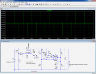
. I'll start experimenting with the first circuit, measure, test, learn and will continue from there on. I do have experience with HV, so that's not the issue.That's nothing really: I had the first schematic in my head, and with LTspice it took less than a minute to transcribe.It's really awesome you taking the time to sketch up these schematics..
The others took a bit longer to develop, but it's fun, and if it can help somebody, it's worth the time.
Note that they have the potential to be tweaked and optimized further: with little effort and additional components, it could become a super-regulator, with ripple rejection well beyond 120dB and output resistance a few milliohm over the whole audio range, but I am not sure you need such performances...
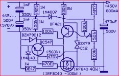
You can try it this way,I didn't build it's rather basic and simple
After all it's for a poweramp,no fancy thing needed,only a stable voltage.
The good thing here is that the case(drain) of the MOSFET is connected to ground,easy cooling.Very important,power lost (heat!) is Vdrop X Iout
Mona
After all it's for a poweramp,no fancy thing needed,only a stable voltage.
The good thing here is that the case(drain) of the MOSFET is connected to ground,easy cooling.Very important,power lost (heat!) is Vdrop X Iout
Mona
Attachments
Hi
If i can say, don't use OP in floating... this is a nightmare.
Why ? you're never sure of voltages, and you cannot tune and test with scope...
What do you want ? kill the noise
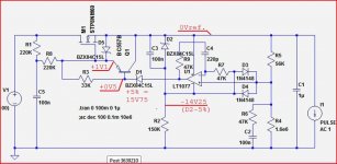
i propose you this one :
What is important :
- You don't set the output voltage precisely, but you kill the noise, that's all that matters in tube amp
- there is a small filter in the feedback to prevent oscillating,
- the op amps are referenced to the ground, and D17 protects against overvoltage, D8 and D7 too.
- the op amp acts through the grid of IGBT thanks to C5 and C7, any change to out of OP is applied to the gird !
- measure of output voltage is like the same, thanks to D16 and D15 (across R17 and R18 is 400 - (200+150) = 50 -> you tunes the U3.3 to +5V (reference voltage)
- don't forget D11, if there is internal diode or not, it's better to protect from output capacitor still charged.
- current limit qith Q1 and R8
This one worked very well on my amp.
If i can say, don't use OP in floating... this is a nightmare.
Why ? you're never sure of voltages, and you cannot tune and test with scope...
What do you want ? kill the noise
i propose you this one :
An externally hosted image should be here but it was not working when we last tested it.
What is important :
- You don't set the output voltage precisely, but you kill the noise, that's all that matters in tube amp
- there is a small filter in the feedback to prevent oscillating,
- the op amps are referenced to the ground, and D17 protects against overvoltage, D8 and D7 too.
- the op amp acts through the grid of IGBT thanks to C5 and C7, any change to out of OP is applied to the gird !
- measure of output voltage is like the same, thanks to D16 and D15 (across R17 and R18 is 400 - (200+150) = 50 -> you tunes the U3.3 to +5V (reference voltage)
- don't forget D11, if there is internal diode or not, it's better to protect from output capacitor still charged.
- current limit qith Q1 and R8
This one worked very well on my amp.
don't believe stability with most spice op amp models when supply floats/modulates, many don't even pull output current from their supply pins - it comes from spice node 0 in most manufacturer macromodels
I would look at Kevin Gilmore's electrostatic headphone amp supply regulator circuits for practical examples
I would look at Kevin Gilmore's electrostatic headphone amp supply regulator circuits for practical examples
don't believe stability with most spice op amp models when supply floats/modulates, many don't even pull output current from their supply pins - it comes from spice node 0 in most manufacturer macromodels
I would look at Kevin Gilmore's electrostatic headphone amp supply regulator circuits for practical examples
You're so right. Simulation is a trap, first you must control every aspect, and then maybe simulate. But don't fall in this trap !
Spice can better reflect the real world - with good models
mistreating floating supply effects/supply pin currents are a specific weakness in generic op amp modeling with Boyle derived op amp models that everybody uses by default
both AD and TI have published op amp modeling app notes explaining the issues, showing better op amp macromodels
but they both continue to publish the worse spice models even for recent op amps
The LT1077 model from Linear is correct in this respect, and the LM358 model I have used is also corrected.don't believe stability with most spice op amp models when supply floats/modulates, many don't even pull output current from their supply pins - it comes from spice node 0 in most manufacturer macromodels
An alternative discrete option is the simple series reg: http://www.diyaudio.com/forums/power-supplies/198986-simple-hv-series-regulators.html
It is tested and proven, requires no voltage translation or auxiliary supplies and has decent enough performances.
Attachments
I do not see how it can work- current limit qith Q1 and R8.
+1I do not see how it can work
And I don't see the use of Q1 in your last post
D1 somewhat lower voltage perhaps ?
Mona
Last edited:
And I don't see the use of Q1 in your last post
No, Q1 serves to improve the ripple rejection.
D1 allows the gate voltage to go more positive than its source, which is necessary for enhancement MOSD1 somewhat lower voltage perhaps ?
OK,where do I see a problem.Elvee said:D1 allows the gate voltage to go more positive than its source, which is necessary for enhancement MOS
A drawing shows it better
With a bit of bad luck the MOSFET continues to conduct when not desired.The voltages assume that the output of the opamp goes all the way down.If it doen't it is even more than 1V1 at the gate
Without Q1 you gain 0V6.
Thats why I suggested a somewhat lower voltage for D2,especialy with Q1 in the circuit.
Mona
Attachments
Hi
If i can say, don't use OP in floating... this is a nightmare.
Why ? you're never sure of voltages, and you cannot tune and test with scope...
What do you want ? kill the noise
i propose you this one :
An externally hosted image should be here but it was not working when we last tested it.
What is important :
- You don't set the output voltage precisely, but you kill the noise, that's all that matters in tube amp
- there is a small filter in the feedback to prevent oscillating,
- the op amps are referenced to the ground, and D17 protects against overvoltage, D8 and D7 too.
- the op amp acts through the grid of IGBT thanks to C5 and C7, any change to out of OP is applied to the gird !
- measure of output voltage is like the same, thanks to D16 and D15 (across R17 and R18 is 400 - (200+150) = 50 -> you tunes the U3.3 to +5V (reference voltage)
- don't forget D11, if there is internal diode or not, it's better to protect from output capacitor still charged.
- current limit qith Q1 and R8
This one worked very well on my amp.
note : Q1 is a NPN and not a PNP ! (wrong schematic version)
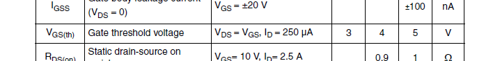
Min guaranteed threshold voltage for the STP8NM60 is 3V. That is a ~300% margin.If it doen't it is even more than 1V1 at the gate
If you're still unhappy (or
) with it, or keen on nitpicking, you can opt for a 13, 12 or even 10V zener, you are free to do so, it will not change anything to the operation of the circuitAttachments
The datasheet has the answer: at temperatures >150°C, the Vgs correction ratio is ~0.7.What to expect with Vds of 50V or more and perhaps 120°C ?
This is still 200% margin, supposing the BC557 remains at 27°C. Anyway, a 10V zener can do no harm (or good in this case, except reassure anxious minds which is certainly worthwhile after all)
I've successfully 'breadboarded' the circuit with the BC557 for ripple rejection. The LT1077 performs very well. Total ripple rejection is around -90dB, which is great! Any ripple seems to come through the MOSFET, not the circuit.
I've also reduced D2 to a 12V zener. My IRFBC40 has a lower Vgs threshold.
I cant get the LM358 to regulate though. I reduced R2 to 120k and R5/R4 to 28k and 1MEG respectively (different ratio due to the 12V zener) to get enough current to the opamp, but no succes. Any tips?
I've also reduced D2 to a 12V zener. My IRFBC40 has a lower Vgs threshold.
I cant get the LM358 to regulate though. I reduced R2 to 120k and R5/R4 to 28k and 1MEG respectively (different ratio due to the 12V zener) to get enough current to the opamp, but no succes. Any tips?
Last edited:
Yeah my bad. D2 sets the opamp rail differential, but the edit button was already gone. But still, the LM358 will not regulate, no matter what I try with my limited knowledge. Smaller feedback resistor(s), properly terminated the unused connections, more available current...
Once I pop the LT1077 back in, everything is fine.
Once I pop the LT1077 back in, everything is fine.
When you say it doesn't regulate, is the output voltage zero, maximum or some intermediate value?But still, the LM358 will not regulate, no matter what I try with my limited knowledge.
I suppose you're aware that LM358 and LT1077 have a different pin-out, but let's not leave any turn unstoned....Once I pop the LT1077 back in, everything is fine.
I'll try to breadboard it myself ASAP, but in the mean time, you can measure the voltages at every node wrt GND and write them on the schematic, this should help to trace the origin of the problem
- Status
- This old topic is closed. If you want to reopen this topic, contact a moderator using the "Report Post" button.
- Home
- Amplifiers
- Power Supplies
- CCS + Zeners or resistors for 450V reference