One more note, there are proceedures for working with high voltage circuits such as only use one limb at a time, always discharge the circuit before touching it, and so on. I used to fix arcade machines, and working on monitor chasis was common. Talk to a TV technichian. Picture tubes are giant capaicitors that work with up to 60KV or higher and must be handled carfully and discharged properly. For example, flyback transformers produce very little current, but lots of volts and can be quite dangerous if a tube discharges through you. Same safty proceedures apply here.
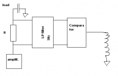
Because the amp's load will be 100% capacitive , i was thinking about a DC leakage detector.In the case a human touches the output , DC current starts to flow through R , and after some time comparator reacts and drives the relay.
It is a very basic schematic - just the idea.
Regards,
Lukas.
It is a very basic schematic - just the idea.
Regards,
Lukas.
Attachments
Greetings from Norfolk
Things just seem to get worse ! If the load is 100 % capacitive you must now consider how you will discharge this capacitor, under all conditions, e.g. if a fault occurs, if it becomes detached from the amplifier, etc.
Also, in your proposed DC detector, have you any idea what level of rejection your filter will need ? Start by working this out, together with considering what components you are going to include in this circuit. It will almost certainly have to be passive (R, C and L ) then you have additional components which are operating at the high voltage which it is supposed to be protecting you from in the amplifier and load.
You realy should take advice on the saety aspects of this type of circuit, you are currently trying to make it safer, but probably increasing the risks !
Fried engineers do not perform well.
Richard
Bazukaz said:Because the amp's load will be 100% capacitive , i was thinking about a DC leakage detector.In the case a human touches the output , DC current starts to flow through R , and after some time comparator reacts and drives the relay.
It is a very basic schematic - just the idea.
Things just seem to get worse ! If the load is 100 % capacitive you must now consider how you will discharge this capacitor, under all conditions, e.g. if a fault occurs, if it becomes detached from the amplifier, etc.
Also, in your proposed DC detector, have you any idea what level of rejection your filter will need ? Start by working this out, together with considering what components you are going to include in this circuit. It will almost certainly have to be passive (R, C and L ) then you have additional components which are operating at the high voltage which it is supposed to be protecting you from in the amplifier and load.
You realy should take advice on the saety aspects of this type of circuit, you are currently trying to make it safer, but probably increasing the risks !
Fried engineers do not perform well.
Richard
Lukas,
this is not very promising!
The suggested "safety circuit" you presented is NOT good, a human body do in fact decrease in impedance both by voltage and frequency!
I would like to correct CBS, but just slightly, 10 mA and lower(especially under some second) is not really deadly (I'm currently reading up on this subject, again), but if the current goes from hand to hand through your chest it can paralyse your breathing musculatur and in worst case you need external aid to kick start your breathing ability.
10 mA and above gives rythm disturbans in your hart if it's continuing from some second and more and it's hard to control your muscles. Couple of mA is not dangerous at all for the human, but it hurts and can make one to jerk, in worst case you touch another part of your circuit that is even more danger.
Just don't forget that you have the rail voltage before the CCS that is not current limited, and if you touch that you are PofDM!
So on to the circuit, you have been quite reluctant, would like to tell us what you are going to do with your monster, drive ESL/planars?
Secondly skip that upper NPN for a PNP or P-ch FET!
Cheers Michael
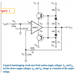
I have found a very interesting article about bootstrapping op-amps :
http://www.edn.com/article/CA45890.html
It could be a workaround of all of my problems.
Regards ,
Lukas.
http://www.edn.com/article/CA45890.html
It could be a workaround of all of my problems.
Regards ,
Lukas.
Attachments
the fundamental problem of making a relatively linear hi V swing output stage is uchanged, only the position of the op amp is different
also simulation becomes much more difficult, the vast majority of op amp models in spice don't treat the pwr pins correctly in either loop gain/dynamics or correct current flows
any op amp model that has spice node 0 (= global ground) in it is almost certainly wrong to the point of unusablity in modeling power supply bootstrapped circuits
Ultima Thule said:Lukas,
this is not very promising!
The suggested "safety circuit" you presented is NOT good, a human body do in fact decrease in impedance both by voltage and frequency!
I would like to correct CBS, but just slightly, 10 mA and lower(especially under some second) is not really deadly (I'm currently reading up on this subject, again), but if the current goes from hand to hand through your chest it can paralyse your breathing musculatur and in worst case you need external aid to kick start your breathing ability.
10 mA and above gives rythm disturbans in your hart if it's continuing from some second and more and it's hard to control your muscles. Couple of mA is not dangerous at all for the human, but it hurts and can make one to jerk, in worst case you touch another part of your circuit that is even more danger.
Just don't forget that you have the rail voltage before the CCS that is not current limited, and if you touch that you are PofDM!
Cheers Michael
On further research I stand corrected. It seems that 20mA is obtainable before ventricular fibrillation takes place for AC currents. Actually higher for DC, according to this article referring to electric fences...(http://www.electricfencingdepot.com/page.php?pid=siteInfoItem&sinfid=18) This of course for less than one second. The problem is, higher voltage has the tendency to hold one to it. A longer exposure time changes everything though. This, I think seems consistent with what you are conveying, Michael. I'm sure there are many other references as well. Still, the voltages described in this circuit could be dangerous if not handled properly. I just wanted to make the general point that if Lukas is not experienced with HV, he might consider working with someone who is for his own safety.
") Not to shoot him down, but I would hate to hear that one of our DIYaudio members inadvertently checked out because of an accident with a project they were constructing.
Not to shoot him down, but I would hate to hear that one of our DIYaudio members inadvertently checked out because of an accident with a project they were constructing.Thanks for all of your help,
For now i am working with a lower voltage version(300V currently),
and the schematic is very simple.However , the results are just opposite to what LTSpice(and my mind) predicts :
1.Distortion decreases with output voltage, while simulations show just opposite;
2.distortion decreases with frequency , from ~0.1% @100Hz to 0.02% @ 10kHz; (largest distortion is @ 50Hz).
3.I tried both current source version and a passive load - no difference observed;
When i connect output of the amp to my sound card
i see a 10-20 db increase of noise at low frequencies(-90db @ 50Hz).
Can it be somehow related with increasing distortion near 50 hz(mains hum ?).
Driver IC power supply is regulated for sure.
How can all this be explained ? Something wrong with board layout ?
Best regards,
Lukas.
Attachments
Hi Lukas,
It probably isn't so much the board layout, but the ripple caused by the rectifier and a loaded filter capacitor. Try using a voltage regulator as the voltage source for V1 and see if the distortion decreases. Are you using a bridge rectifier(full wave)?
BTW, it is better to start small, then work your way up.
Thanks!
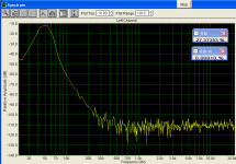
The filter capacitor was loaded significantly.It was only 10 uF.After putting in a 2x470uF in series from an old PC supply, the distortion decreased by much.It is now < 0.03% in the audio spectrum.The IMD is 0 (?).
Square wave has some "Ringing"(As i understand irregularities near wave corners), so the compensation may need to be increased.
I wonder that sound card is capable of producing square.
One thing i really don't understand is a very strange measurement results in SpectraPlus.I think it is program bug , and is only observed this for very low frequencies.( THD vs THD+N).
Attachments
Hi,
Thanks for all of your help,
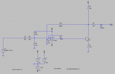
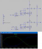
I have finally drawn the following schematic.I have also tried it in real world, and it worked well.
However , in simulations , when the amp is overloaded , i get some high frequency artefacts.There are no such an artefacts for square wave(assuming an amp is not overloaded for sure).These spikes occur when either rail swings to ground , and are seen by the other amp, so i get it at both outputs simulatenously. I tried simulating with some compensation added, but it does not solve problem completely , while greatly increasing distortion.
Regards ,
Lukas.
Thanks for all of your help,
I have finally drawn the following schematic.I have also tried it in real world, and it worked well.
However , in simulations , when the amp is overloaded , i get some high frequency artefacts.There are no such an artefacts for square wave(assuming an amp is not overloaded for sure).These spikes occur when either rail swings to ground , and are seen by the other amp, so i get it at both outputs simulatenously. I tried simulating with some compensation added, but it does not solve problem completely , while greatly increasing distortion.
Regards ,
Lukas.
Attachments
Thanks,
Actually , i have tried with real load of 100pF capacitor only , and used my cheap integrated sound card for testing.The prototype has only one channel(no bridging) , and there is no LM833 preamp to drive the output to full power. I am wondering if bridging would give more problems.
I now working with PCB , but , before etching, i would like to know if it is an easy way of solving the problem i mentioned...
Any other improvements/suggestions are welcome.
Regards ,
Lukas.
look at the op amp ouputs at the Q bases when clipping - remove esl Cload to see each sides response without the other interferring
maybe helpful: bounding diodes in local negative feedback around the op amps to limit voltage swing when clipping - probably 2 antiparallel strings of ~ 3x small signal diodes in series between op out and op -in
the lm318 is a screwy op amp, wether it will be unity gain stable with the bounding diodes is questionable
Thanks for help,
After removing the load , the problem only arises when output tries to swing below ground.Increasing C2 and C7 to 500pF almost diminishes the artefact(still not completely).But i don't want to load my amp with additional 500pF.
I assume i am having problems with stability...
Actually , i will use 2SC3675 transistors , but , unfortunately , i cannot find their models on the web. Maybe somebody knows where to get a free model-generator program ?
Lukas
After removing the load , the problem only arises when output tries to swing below ground.Increasing C2 and C7 to 500pF almost diminishes the artefact(still not completely).But i don't want to load my amp with additional 500pF.
I assume i am having problems with stability...
Actually , i will use 2SC3675 transistors , but , unfortunately , i cannot find their models on the web
. Maybe somebody knows where to get a free model-generator program ?Lukas
you can "split" your differential load C, put 2 2x Caps in series and ground the middle, this will give similar load as seen by each side in the bridged config but eliminates the coupling for debugging
square waves are not good for investigating clipping behavior, they can cause the operating point to blow right past possible instablities
use sines and vary the peak to just below to well above clipping in small increments, repeat over a range of frequencies
square waves are not good for investigating clipping behavior, they can cause the operating point to blow right past possible instablities
use sines and vary the peak to just below to well above clipping in small increments, repeat over a range of frequencies
jcx said:use sines and vary the peak to just below to well above clipping in small increments, repeat over a range of frequencies
Yes, I would echo that. Start with 1kHz to find maximum output and general clipping behaviour, then drop to somewhere in the 30Hz region and repeat, then try 10kHz.
- Status
- This old topic is closed. If you want to reopen this topic, contact a moderator using the "Report Post" button.
- Home
- Amplifiers
- Solid State
- CCS question