The shunt regulators are either 1.25 or 2.45V(LM331 etc) reference.
You would improve the amplifier by making the output a cascode, otherwise the opamp is going to struggle with Miller capacitance. This helps with the transistor voltage rating as well.
High voltage transistors have very low beta, I remember using TV line outputs with about 3
You would improve the amplifier by making the output a cascode, otherwise the opamp is going to struggle with Miller capacitance. This helps with the transistor voltage rating as well.
High voltage transistors have very low beta, I remember using TV line outputs with about 3
Is Miller capacitance the same as Cob in datasheet ? if it is of a picofarad range , then it should not be a problem for an opamp to drive.
Also , what do you call beta ?
What is cascode ?
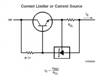
Again , what R should be used ? To supply shunt regulator with enough current ?
Thanks,
Lukas
Also , what do you call beta ?
What is cascode ?
Again , what R should be used ? To supply shunt regulator with enough current ?
Thanks,
Lukas
Hi,
Cob is the capacitance that gets multiplied by the Miller effect.
You will often find that the Cob is between 3pF and 500pF for BJTs and slightly higher for FETs.
For good high frequency amplification you want as low a Cob as is necessary for the circuit to work without loading the previous stage excessively.
If your amp is working to a bandwidth of 20kHz you would expect very good performance to 10 times this and adequate performance to about 100 times this.
Now check the current into the Cob at 200kHz and see if it can be supplied by the previous stage.
Look up Cascode. It is a circuit for applying a fixed voltage to the lower active device. It also happens to isolate the Miller effect from the lower device (because the voltage does not vary) allowing very good high frequency performance.
The R? is chosen to supply the current the voltage ref needs. Use ohms law to calculate it's value. You will also need to calculate the power dissipation of the resistor and select a resistor to match or exceed it by a factor of two to three if you want it to run cooler or be less affected by temperature coefficient.
Thanks for help,
One more question - can i substitute LM431 with LM385 in the circuit below ? LM431 requires too much current , and LMV431 is unavailable in my country.As i understand , these regulators are actually very simillar ? Output current of CSS is ~ 15 mA.
Regards ,
Lukas
One more question - can i substitute LM431 with LM385 in the circuit below ? LM431 requires too much current , and LMV431 is unavailable in my country.As i understand , these regulators are actually very simillar ? Output current of CSS is ~ 15 mA.
Regards ,
Lukas
Attachments
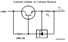
Actually , i it is only a half of bridge amp.I will bridge it.I need +700 V supplies anyway(I expect to get ~1300 V swing at output).
The transistors i found are 2SC3866.I tried with current source and adjusted sound card's input correctly.The distortion is (Very strange?)
falling with frequency(0.3% @ 1 kHz and 0.02% at 10 kHz).I think this can be caused by half-wave supply rectification.
Lukas
The transistors i found are 2SC3866.I tried with current source and adjusted sound card's input correctly.The distortion is (Very strange?)
falling with frequency(0.3% @ 1 kHz and 0.02% at 10 kHz).I think this can be caused by half-wave supply rectification.
Lukas
Hi,
Now i have another problem to workaround.In simulation model,
TL431 & Q2 works as a current source .The current is not very stable and modulates from around 9.5 to ~10.5 mA with audio signal.
How to make the current more constant ? CCS circuit is taken from the datasheet.
Also, will the TL431 be stable in this circuit ? if not , what should be done to stabilize?
Regards,
Lukas
Attachments
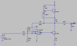
Total current source is Current in Q2 + Current in TL431.
Current through Q2 is stable ~10 mA.
But how about the current in R1 and TL431?
The will not stay same.
They will change with output voltage.
Because voltage across R1 will change.
You can replace R1 with two Resistors in series.
Then you can 'bootstrap' - with a Capacitor,
from point between these 2 Resistors, to Output.
Capacitor value could be like 10 uF, I think.
Value depends on value of those two resistors.
This Cap will keep voltage across Resistor feeding TL431 constant.
And so will current going through TL431 be constant.
And also total current: current in Q2+TL431
Hi,
what voltage is feeding the 150k to tl431?
What current then flows?
correction to my first post
TL431 operating current is 1mA to 100mA.
But may work down to 0.4mA if it meets typical specification (risky).
Q. how does the ccs work?
2.5V (Vref) across the Re giving 10mA.
What follows with the required Vbe and how does it hold it?
Could an explanation here identify the stability problem?
Lineup has noticed that the ccs leg through q2 is contaminated by adding in tl431 current. This is not the same as the datasheet circuit.
Greetings Lukas
I have only just come upon this thread, and I think that you should seriously consider what you are building, with your apparent lack of knowledge of transistors etc.
The voltages that will be present in the circuit, particularly if you 'bridge' two amplifiers will be very high (you quote 1300 V).
This is a voltage well above the normal for most amplifier designers, and would cause concern in any professional design team. You may well run into problems with the breakdown of insulation and arcing of the voltage between points.
From the tenure of your questions I doubt that you have the background knowledge to safely resolve the problems you face.
If it is essential that you build this odd amplifier I would strongly recomend that you get local professional assistance from some one who is familiar with the precautions necessary when working with the voltages you quote.
I don not wish to damp your enthusiasm but I prefer to communicate with live designers, not their spirits.
Richard
Thanks,
I am serious with my design and i know that it can be deadly.
However , the output current will be limited by current source(~10mA) and output capacitors, so i assume it is probably not more dangerous than AC mains.
My first try failed with high values of distortion(~0.3%) , but now the simulations show that i highly "overcompensated" the first circuit, making it slow.
Also i have read some info about Cascoding , but in simulations i was not able to detect any advantage - probably otherwise.
For sure simulations may be wrong.
Now i would like to ask : lets say , the transistor has a Cob of 50pF.
What capacitance will the driver IC see ? Is it related with voltage gain ?
Thanks for support,
Lukas .
lineup said:
You can replace R1 with two Resistors in series.
Then you can 'bootstrap' - with a Capacitor,
from point between these 2 Resistors, to Output.
That's not really a good idea, I guess you wasn't at your sharpest mode..
")
Cheers Michael
Ultima Thule said:That's not really a good idea, I guess you wasn't at your sharpest mode..
Cheers Michael
Enlighten us, please, Michael.
If you say only 'is not a good idea',
you should really give a good motivation for it.
I know you know what most of us do not know.
So why keep your secret?
Also,
I am sure you have an idea that is better.
And that you can help to advice Bazukas.
This is what we want to do, isnt it?
To the best of our knowledge and ability.
I guess you weren't at your most helpful mode..
Regards
lineup
lineup said:
I guess you weren't at your most helpful mode..
Regards
lineup
Intentionally not..!
A good teacher don't throw away the answer without pointing out the eventual fault and letting the pupil think first for a while!
Cheers Michael
just came across new ixys depletion mode mosfets, at these pwr and idss rating they change the game for hiV ccs
http://www.ixys.com/98861.pdf (1000V available too)
with -2.5 Vgs min you could run a lm334 in the source to get pretty high Zout with little complexity
http://www.ixys.com/98861.pdf (1000V available too)
with -2.5 Vgs min you could run a lm334 in the source to get pretty high Zout with little complexity
Bazukaz said:Thanks,
I am serious with my design and i know that it can be deadly.
However , the output current will be limited by current source(~10mA) and output capacitors, so i assume it is probably not more dangerous than AC mains.
Thanks for support,
Lukas .
On the contrary, the current through your body(resistor) is determained by the voltage accross it(Ohms Law). And 10mA is more than enough current to be deadly. AKA cause cardiac failure!!!!! Also DC current can be more dangerous than AC. The mains is a lower voltage so that limits the current. If you have 10X the voltage, then 10X the current on that resistor. Current is determained by Ohms Law, not by voltage. Where 120V may give a good tingle, 1200V may cause you to push up a daisy or two.

 I agree with Richard, if you insist on using this voltage, PLEASE be careful!!!! You can't be killed by a simulation, but simulations are far from real.
 If you drop these voltages across your chest from one arm to another, we may not hear anymore posts from you.
And this would be very unfortunate. Not trying to discurage you but you can't argue with physics.ilimzn said:
If only the facts were correct...
Lower output impedance increases dampiing factor (or were you talking about Q?). Current source is nor necesairly used only when you want high gain, but also when you want a better defined slew rate and/or output voltage swing. Depending on what amplifying device you use for the other end, a current source may linearize it and produce lower distortion.
Would a current source improve this amps PSRR even with a op amp at HF over a resistor load ?.
Was thinking this could be quite important as smoothing or regulation at high voltage is more troublesome. Big voltage caps, balance resistors and maybe a multiplier etc.
- Status
- This old topic is closed. If you want to reopen this topic, contact a moderator using the "Report Post" button.
- Home
- Amplifiers
- Solid State
- CCS question