Hi,
I am trying clipping for sine wave .A very slight clipping does not cause any problems. In the case of harder clipping , op amp will try to turn Q on even more , and current at base increases dramatically.Is it ok to stress op amp so , or they are rated at continous short circuit operation ?
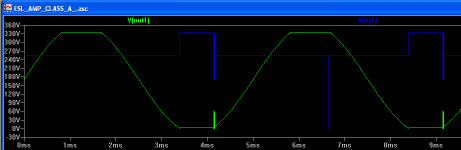
I have attached a clipping graph and base current of one channel , with ESL load disconnected , leaving only 50pF to ground.
I cannot center-tap load ESL , because it will have to be connected it to ground through EHT supply(HV+20 mOhms).
Thank you for help,
Lukas.
I am trying clipping for sine wave .A very slight clipping does not cause any problems. In the case of harder clipping , op amp will try to turn Q on even more , and current at base increases dramatically.Is it ok to stress op amp so , or they are rated at continous short circuit operation ?
I have attached a clipping graph and base current of one channel , with ESL load disconnected , leaving only 50pF to ground.
I cannot center-tap load ESL , because it will have to be connected it to ground through EHT supply(HV+20 mOhms).
Thank you for help,
Lukas.
Attachments
Hi again,
I have another question.If i drive a capacitive load with an A class amplifier , does the power dissipation of output transistor/load resistor increase ? The output transistor , 2SC3675 , is rated only at 10W@25 C, and ~5W@85 C, and will be running at around 4 Watts.Is it possible that the transistor's power dissipation can be exceeded while driving capacitive load ?
Best regards,
Lukas.
Resistive loads are always the best case as current is maximum when voltage across the transistor is minimum. Reactive loads can be much worse. I suggest you have a play with the free version of the simetrix simulator, which makes it easy to look at power disipation in a device.
Hi Bazukaz,
what is that glitch in the base current as the stage comes out of negative clipping?
What temperature (Tc) will the 2sc3675 be running at when heatsinked and @ 4W dissipation?
Regarding output device dissipation:-
Look up the temperature derating curve to find the proportion of total power you are permitted at your running temperature.
Then look up the SOAR for the range of voltages (Vce) you are asking 3685 to handle and find the maximum current (Ic) permitted at each voltage. Now apply the derating to the extracted SOAR currents. These are your limiting currents and voltages for your operating conditions.
The instantaneous dissipation is current times voltage. These are easy to plot for resistive loads.
You'll find power varies with the phase of the signal. You will also find that power varies with the amount of current delivered to the load.
Now you enter the realm of reactive loads - I suggest you sort the DC and resistive first.
Hi,
Thanks for your valuable reply.I looked in U and I curves for my transistor in simulator and then in datasheet.
It appears that it is within limits,except for these current spikes that occur when hard clipping.I wasn't able to avoid them , only decrese by increasing C2 and C4 ...
How to make rid of it ?
Regards,
Lukas.
Hi,
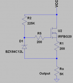
how can you dissipate 4W in your output transistor with a 30k collector load?
What is your +Vrail voltage? 500V?
Output impedance is a bit high and that 0.1uF will roll off the bass reponse a bit early.
Put a sensible load on your output//cable capacitance and you'll see what I mean.
how can you dissipate 4W in your output transistor with a 30k collector load?
What is your +Vrail voltage? 500V?
Output impedance is a bit high and that 0.1uF will roll off the bass reponse a bit early.
Put a sensible load on your output//cable capacitance and you'll see what I mean.
Thanks for help,
I didn't think about low-roll-off.
Actally , i am planning supply voltages of up to 700V. Now , after reading SOA curves of few transistors , i have found out that FETs are probably better in this situation. Is this true ? What about IRFBG20s?
Regards,
Lukas.
I didn't think about low-roll-off.
Actally , i am planning supply voltages of up to 700V. Now , after reading SOA curves of few transistors , i have found out that FETs are probably better in this situation. Is this true ? What about IRFBG20s?
Regards,
Lukas.
AndrewT said:Hi,
yes, in general FETs don't suffer much reduction in power ability at high voltages.
Simply say FETS donot suffer from Second Breakdown Voltage...because that's the limiting factor in BJT's power handling capacity at higher voltages
K a n w a r
Workhorse,
why do you invent words I did not say.
Behave yourself.
You have no right to post this statement:-
I said.
I DO NOT AGREE with you.
why do you invent words I did not say.
Behave yourself.
You have no right to post this statement:-
I think now you completely agree
I said.
in general FETs don't suffer much reduction in power ability at high voltages.
I DO NOT AGREE with you.
AndrewT said:Workhorse,
why do you invent words I did not say.
Behave yourself.
You have no right to post this statement:-
I said.
I DO NOT AGREE with you.
Hi AndrewT,
I donot invent these words, Yes but discovered right from your statements .....
Kindly Explain what is the meaning of "FETs donot suffer reduction in power handling at higher voltages" so i can agree with you....
The Girl I am in love with also says "I DO NOT AGREE WITH YOU" whenever i said to her that I love her, because SHE is in love with someone else who has already heart breakened her by marrying someother girl....but Andrew Do you know that in love you cannot control the heart because you have no control over it after all.........
cheers,
K a n w a r
")
Maybe you could build an "amplifier" to amplify DC from the zener reference to suply the "rail" voltage, NF loop and all. From here there is no end...  Only to better PSRR. This only complicates everything, but if you are just making something for yourself, why not make it better
Only to better PSRR. This only complicates everything, but if you are just making something for yourself, why not make it betterHi,
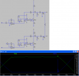
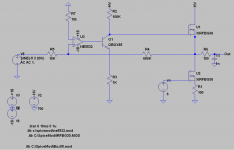
I have drawn another circuit.
Do you think it is possible to stabilize it , without losing too much open loop gain at high frequencies ? I tried to put a small cap(~250pF) across -in and out of op amp, but this cuts too much open loop gain , so i end up with high distortion at high frequencies.Lower cap values don't work.
By the way , what do you think about this circuit ?
regards,
Lukas.
Attachments
- Status
- This old topic is closed. If you want to reopen this topic, contact a moderator using the "Report Post" button.
- Home
- Amplifiers
- Solid State
- CCS question