Unclejed,
Thanks for your reply.
In practice I drive it from a tube stage and in test situations from a 50 Ohm function generator.
Capacitances (voltage dependant off course):
2SA side: Pre driver 2.5pF, Driver 25pF, Output device 500pF
2SC side: Pre driver 1.8pF, Driver 16pF, Output device 250pF
Things are even more worse than you sugested! I have measured the total beta. It is 6,400,000!!!
Peter
")
pietjers said:Bob,
I did a quick read of the part about distortion measurement on your web-site. It takes quite a lot of experience and specialized equipment to analyse the distortion behaviour of an amplifier stage. What can one do with only a function generator and an oscilloscope?
It can indeed take a lot of equipment, but as someone else suggested, nowadays the less-equipped DIYer can look to PC-based soundcard solutions, combining quality soundcards with appropriate software. I have not delved deeply enough into this area yet, but I have used the Juli@ sound card with some software like Visual Analyzer.
The key, I think, is in building some purpose-built DIY hardware to enhance the capability and performance of the PC-soundcard arrangement. One could build a box to handle the I/O interfaces to the amplifier under test.
Also, one could build the Distortion Magnifier (DM) that I use to enhance the distortion floor and spectrum analyzer floor of the PC solution. The Distortion Magnifier is a purpose-built piece of equipment that essentially does a carefully level and phase-matched subtraction of the input of the amplifier from the scaled-down output of the amplifier to magnify distortion by a factor of 10 or 100. Things like this could go a long way to allowing one to do fairly good measurements with a decent sound card and software.
Cheers,
Bob
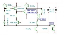
Lumba Ogir said:Gentlemen, single ended, bridge load, what are the possibilities for biasing the current generators?
You may try one of these...
Attachments
ppl said:
I would put some resistors between the upper and lower cascode's for the pre-drivers and drivers you would be surprised at how quick this topology will oscillate without them.
pietjers said:PPL,
It’s funny how similar your designs and my design ideas (are planning to give them a try in real life) are. The fun is that I hadn’t opened the shortcut in your post #51 before I posted my second hand drawn schematic. Saw it after posting when I was re reading the last posts.
I have an old Tektronics AA501 Distortion Analyser plug in. But the pushbutton switches are quite bad and not easy to get okay with contact cleaner. This analyser has a function output showing filtered distortion. But it’s very important to have a low distortion generator because normal generators have so much distortion that it will dominate the measurement. Must have also a Tek low distortion generator somewhere……., will perform a search soon.
Most difficult part will probably be to get everything stable!! I have built already the inner part of the cascode (the triple darlington part) and the only way to get it really stable is be means of the resistor at the input. From 2k and up it’s stable. Below 2k and especially below 1k the circuit starts to oscillate. I have tried about everything one can think of to control HF stability, but always the input resistor turned out to be the best and most effective solution.
What I tried (al the time with a square wave signal of a few V and a frequency of about 200kHz at the input to be able to closely observe ringing and oscillation behaviour):
• Adding base stoppers. Did not really improve stability. These resistors are only effective in the VHF region I think. The drawback of base stoppers (especially at the output devices) is that the output impedance of the circuit rises (want to use it without feedback).
• Adding capacitors from the base of the pre-drivers, drivers and output devices to supply voltage (tried it one by one). Found that their values are quite critical. Too small, little or no improvement. To big => instability. When about optimal still certain circumstances where the idling current starts to quickly run away for unknown reasons.
• Adding small capacitors from input to ground is a little playing with fire. Can also easily cause instability.
• Adding a small capacitor from output to input. Didn’t add much stability either. Perhaps I should have added a series resistor with the capacitor here.
But however I will try to get it up and running!
If you have suggestions, please let me know. I have already heard the suggestion to add resistors between the upper and lower half of the cascode, so I have added those.
Peter
An externally hosted image should be here but it was not working when we last tested it.
Type 1 Circuit works great in my application as a headphone Driver and or low power Loudspeaker amp (About 10 Watts into 8 ohms on +/- 20 volt Rails)
Type 2 circuit displayed most all the qualities your circuit dose and i also tried all the compensation methods you did except caps from the Base of the Upper cascode to the Plus Rail because i use a Current source in that location and i don't believe it is a good Idea to put a cap across a Current source. Now this type 2 circuit dose work properly for a few Hours then if you touch any part of the circuit as it is powered up it breaks into oscillation and the Icq goes from 30 mA on the Output transistors to over 2 Amps. and will not pass an AC signal yet DC offset is still low. then touch any part again and the instability stops. Since this issue is apparently thermal and or time related, In addition to the fact that standard compensation methods are ineffective i suspect that in my instance the PC Artwork may be at issue or perhaps alternate Transistor selection however the Chosen devices in theory should be ideal for this application and they also work in the type 1 circuit.
I understand that their are people that question the validly of a tipple darlington string as allot of Phase shift can result from each additional stage, however the Huge amount of Current gain available allows a High impedance lightly Biased Vas stage to be employed, Moreover for an application of using a Tube front End would benefit alot from this high of Current gain and would remove allot of the Load interaction upon the VAS.
The talk of miller capacitance is also not an issue as much as it is with non cascoded Output stages (See Pass).
Regardless of if a tipple Darlington stage is appropriate or not is not my concern hear as similar stages have been done before and apparently there designers were able to make em stable and this is my Goal hear to make The Type 2 circuit stable and if that is not possible revert back to the working type 1 circuit, however i would like to move froward not stagnate on this, Thanks for Reading.
unclejed613 said:so whatever junction capacitances you have, mainly the output devices, gets multiplied by one and a half million, and output device Cbco is about 100pf on average, some higher, some lower. a juncyion capacitance of 100pf in the output stage becomes a miller capacitance of 150uf with that kind of beta multiplication.
In fact, there is an exactly opposite effect. Whatever input capacitance the output devices have, would be divided by total beta of two previous stages (NOT the total of all 3 stages!), i.e. 1000 pF on the output devices would became only a fraction of a pF load for the VAS. However with an increase in frequency the beta drops down and the output devices capacitance loads the VAS more. It is not necessarily a bad thing, thought.
Cheers
x-pro
x-pro said:
In fact, there is an exactly opposite effect. Whatever input capacitance the output devices have, would be divided by total beta of two previous stages (NOT the total of all 3 stages!), i.e. 1000 pF on the output devices would became only a fraction of a pF load for the VAS. However with an increase in frequency the beta drops down and the output devices capacitance loads the VAS more. It is not necessarily a bad thing, thought.
Cheers
x-pro
Thank You
ppl said:I am playing with two types of cascoded output Designs for Headphone use however it is simple to upscale to what you need taking into account the Voltage limitations of the J-FETS used in the casscode current sources.
Type 1 is similar to what (Lumba Ogir) Purposed I did not use any emitter resistors on the Drivers and Pre-drivers and this works good. A constant current source (Not shown) As purposed in one of Mr Passes patents between the Collectors of the lower cascode transistors can be used to ensure glitch free start up but not required.
Type 2 is a more conventional cascode arrangement providing cascoding of the Drivers and pre-drivers to each other. this type is so far as shown proving to have intermittent stability issues, However when it is working it has both better sound and lower measured THD and IMD performance than type 1. Both Circuits show very low distortion and i use the type 1 as a standalone Line driver stage with no gain or overall feedback (I consider Emitter resistors local feedback and thus any circuit using them really can not claim totally feedback free) Pay close attention to the different locations of C8 in the Type 1 and type 2 designs as this location was chosen empirically to make stable. Has more benefit on type 1 topology than type 2 and i believe once the type 2 is made unconditionally stable C8 can be eliminated.
One thing to keep in mind is that Cob increases as Vce decreases and for most power BJT's it takes a more dramatic turn for the worse as Vce drops below 5V, so by cascoding with too low a voltage across the output transistors, you can actually increase the average capacitive load on the driver transistors.
Cascoded power output stages look nice on paper, but making one that performs better (not worse) than a well executed double or tripple EF isn't that easy.
Lumba Ogir said:Hi Glen,
always nice to have you around. How are things going with your non-cascoded project?
Things are going well. When I finish rebuilding my car shed and get all the engines, engine cranes, gearboxes and cra@p out of my electronic workshop shed I'll be able to finish building my 1kW per channel rail tracking (sort of like cascoded) class A EC amp.
Also remember that >Cob with <Vce comes with fT droop as well, so too low a bootstrapped Vce for your output trannies not only gives more input capacitance but less bandwidth too.
Hi Lumba,
maybe it's just me, but I do not understand your schematic. It seems your inputs are the bases of T5/T6, and the bulk on the positive rail might be an output modulated current source. So you take T5 and T6+load as active load? Why the asymmetry with T6 and load in series?
As you see now what the results of my short look are (shockingly incorrect I guess), maybe you could post a short description of what you have in mind about this thing?
All the best, Hannes
PPL,
Perhaps increasing the values of R32, R33 (470 Ohm) helps. In my case series resistance at the input was most effective. Success with getting things stable!
Kleinschmidt,
I agree with you say about Vce. It’s a good idea to increase the voltage of the shunt voltage references with at least a few volt.
Peter
Apperently you and I think alike because changing the value of the Base stopper resistor is my 1st try with these types of instability. but heck ill try say 2.2k and see what happens. I had another Buffer design i did a few years ago require a quite large resistor on the Input transistors base, BTW i use 2 BLUE LED's in series that gives me just over 6 volts as the reference, This should be plenty with these transistors but then again ill try that also thankspietjers said:PPL,
Perhaps increasing the values of R32, R33 (470 Ohm) helps. In my case series resistance at the input was most effective. Success with getting things stable!
Kleinschmidt,
I agree with you say about Vce. It’s a good idea to increase the voltage of the shunt voltage references with at least a few volt.
Peter
I have only little experience in simulating circuits. Never trust the results completely, but perhaps due to my ignorance.
Do you guys think simulation software is a reliable tool in predicting the stability boundaries of a circuit (the above cascode output stage for example)?
Peter
Do you guys think simulation software is a reliable tool in predicting the stability boundaries of a circuit (the above cascode output stage for example)?
Peter
To a somewhat limited extend I'd say yes. One must carefully design in reasonable parasitics (trace/wire inductances and realistic power supply behaviour) and one should make shure that the models reflect at least the device parasitics in a first order approximation (FET models tend to be notoriously bad in this respect). Also the parts should be run under normal operating conditions to partly avoid modelling errors which greatly increase when one leaves typical operation points (say, very low Vce, very low/high currents etc). And then you need to do many Monte-Carlo runs with step/pulse transient runs under many load conditions (true arbitrary output voltages and currents), to look what happens when parameters shift...pietjers said:Do you guys think simulation software is a reliable tool in predicting the stability boundaries of a circuit (the above cascode output stage for example)?
All in all, if you manage that your sim behaves unstable, it probably will in real life also. But you sure can't prove the negative this way.
Spice is generally way better for looking at stability concers that arise from control loops (global feedback) as this is a systems thing, not uncontrolled and complex behaving parasitics.
- Klaus
Peter,
Are the speakers in your avatar yours?
No, it is better to see in practice. These oscillations occur at (very) high frequencies, should not be too hard to tame, use base stoppers for the cascoding transistors.Do you guys think simulation software is a reliable tool in predicting the stability boundaries of a circuit
Are the speakers in your avatar yours?
and in other respects.(FET models tend to be notoriously bad in this respect).
This is an update because in the past week I have built and tested the circuit beneath (only with 10V zeners instead of the 5V references).
What most worried me was circuit stability. Well, I must say that these worries have turned out to be true! This circuit is really very hard to get stable. I tried all of the usual ways to get it right (like described in post #59). It is stable under certain circumstances, but during power-up lots of nasty oscillations can be seen that disappear once it’s settled.
The rejection of AC signals across the output devices is quite good. With 2V AC at the output I measured the Vce (10 V DC) of the output devices to have only 3mV AC (-56.5 dB). It is also rather frequency independent, giving at 1 kHz about the same values as at 20 kHz.
For now it’s too much work to tame this beast, probably I will give it a try later when I have more time to investigate it.
Peter
An externally hosted image should be here but it was not working when we last tested it.
- Status
- This old topic is closed. If you want to reopen this topic, contact a moderator using the "Report Post" button.
- Home
- Amplifiers
- Solid State
- Cascode Output Stages