That's gorgeous, Byrtt!
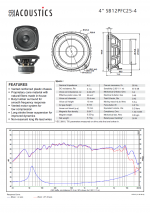
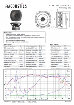
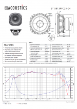
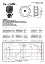
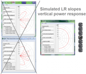
Thanks same goes to your amp and its line array intension, allow me point to SBA have started shipping their PFC series as coxials too, 4/5 inchers is below and by that think it should be possible make one a nice line array that get interesting better power response possibility into XO region than we used to.
Attachments
From BOM:
270R Part No 594-MMA02040C2700FB3 - 0 in stock, factory lead time 69 weeks
220R Part No 594-MMA02040C2200FB3 - 0 in stock
10k Part No 756-WRM0204C-10KFI - qnty 1 in stock
Well, some are in stock but many are not.
Better substitutes for the MELFs appear to be Yageo RT thin film chip resistors in 1206 25ppm. They're readily available and $0.043 ea in 100 off quantities.
Yageo RT Series 25 PPM / C 1206 Thin Film Resistors - SMD | Mouser Australia
Those 4" coax drivers look sexy. Do you have some build plans for them?
Thanks same goes to your amp and its line array intension, allow me point to SBA have started shipping their PFC series as coxials too, 4/5 inchers is below and by that think it should be possible make one a nice line array that get interesting better power response possibility into XO region than we used to.
very cool
")
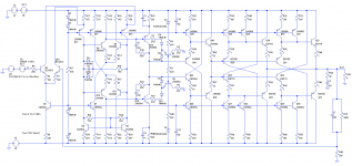
for even more fun, you could add another VAS and output stage driven from the outputs Q19 and Q20 of the diff stage for differential input and output.
hmmm, what else can we do to get this up to 200 ...
mlloyd1
for even more fun, you could add another VAS and output stage driven from the outputs Q19 and Q20 of the diff stage for differential input and output.
hmmm, what else can we do to get this up to 200 ...
mlloyd1
...
There are exactly 100 transistors
Those 4" coax drivers look sexy. Do you have some build plans for them?
So far startplan is order one 5 incher for trials when available local because think price range is spot on for some non-center to center spacing diy fun.
Do you make any larger woofers? Thinking 8" or 10".
-Chris
Not shure if this post was for me (I'm not a employee at SBA)
at present it looks they cooked up to 6 inch into their PFC series and started shipping those, but who knows if there comes bigger ones too or maybe SATORI coxials to compete with KEF.very cool
for even more fun, you could add another VAS and output stage driven from the outputs Q19 and Q20 of the diff stage for differential input and output.
hmmm, what else can we do to get this up to 200 ...
mlloyd1
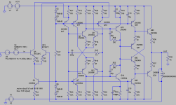
I like where you're going with this... An easy way to blow past 200 transistors is to do discrete opamps rather than the integrated ones. The very same topology I'm using for a power amp, omitting the clipping management and output stages, simulates reasonably well as an opamp - see for example the attached sim - 0.02ppm THD (10KHz 10Vpk into 1K unity gain). As a bonus it's unity gain stable (I calculate 70deg phase margin) and reasonably low (2.8nV/sqrtHz) noise.
And a mere 19 transistors, so ten of them to implement the active filter is just 190, making a total of 290 transistors for the circuit.
Attachments
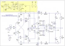
???the sims I’ve run, while wide band, struggle to get better than 0.001% THD and tend to have pretty low input impedance.
With a simple transistor in the input stage, I use to have a normal 10K Input impedance, with a diamond, no problem to get 47K.
May-be this schematic can give-you some ideas ?
(C11 & C12 make an input filter, R14 &r15 dump the diamond witch tend to be "nervous".)
And those threads:
Slewmaster - CFA vs. VFA "Rumble"
200W MOSFET CFA amp
Attachments
Last edited:
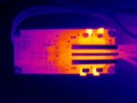
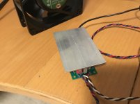
A quick IR photo of the running board, with a simple heatsink (3 x 20mm wide strips of aluminium).
Hottest bits are the 2N3904/2N3906 source/sinks on the output stages, at 60 degrees C. The output transistors are running about 50 degrees.
9mA per output might be a tad optomistic. I might back off from 56 ohms to 68 for the output stage current setting resistors.
Hottest bits are the 2N3904/2N3906 source/sinks on the output stages, at 60 degrees C. The output transistors are running about 50 degrees.
9mA per output might be a tad optomistic. I might back off from 56 ohms to 68 for the output stage current setting resistors.
Attachments
If your heatsinks are at ~60degreesC, then the devices dissipating heat to the heatsinks must be hotter, not cooler than 60....................
Hottest bits are the 2N3904/2N3906 source/sinks on the output stages, at 60 degrees C. The output transistors are running about 50 degrees.................
Maybe Tc~70degreesC depending on Rth c-s.
If your heatsinks are at ~60degreesC, then the devices dissipating heat to the heatsinks must be hotter, not cooler than 60.
Maybe Tc~70degreesC depending on Rth c-s.
The 3904/3906 transistors in the output stages aren't on heatsinks. The BD179/180 devices are. The heatsinks are perhaps 40 degrees, BD179/180's ~50, 3904/3906's ~60.
I'm starting serious work on version 2 of the PCB - an evolution of this one.
Changes are:
Addition of a current sink load for the first stage - this allows me to use the same amp with ~+/-6V to +/-20V supplies, without having to change anything. Plus it doesn't hurt OLG.
A slightly reworked clipping management circuit, to allow for variation in supply voltage.
Reworked compensation, including caps across the VAS transistors, which improves stability without stuffing slew rate - thanks to Dadod for that idea.
Substitution of 2N3904/3906 transistors for the 2N5807 & 5809 transistors in the second stage. Turns out these guys were'n't even a complementary pair, plus they're nowhere near as readily available as the ubiquitous 2N3904/3906. This results in a slight OLG penalty, but I can live with that.
Doubled up output stage current sink/source transistors to reduce dissipation there.
Attachments
Hmmm. Something's not right here.
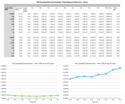
Attached spreadsheet of harmonic measurements at 1KHz, with calculated THD+N. Having attached the heatsink through the week I felt confident to put an 8Ω dummy load on and push it into clipping, which it does at about 8.3V RMS (8.5W) with a +/-18V supply.
However my THD+N measurements are much worse than they really should be - being 20dB higher than the results from a couple of weeks ago with the 47Ω load & no heatsink.
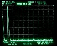
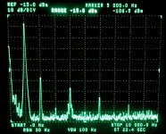
If you look closely at the figures (I've also attached crappy screen photos of the output spectra at 5 V RMS into 8Ω with and without the notch) it's pretty-much all H2, H4 etc. I'm wondering if perhaps I've popped one of the output transistors while playing into a 4Ω speaker with no heatsink over the last couple of weeks. There's plenty about my test setup that could be contributing, too - it's something of a quick lashup.
Anyway, I'll investigate further.
Attached spreadsheet of harmonic measurements at 1KHz, with calculated THD+N. Having attached the heatsink through the week I felt confident to put an 8Ω dummy load on and push it into clipping, which it does at about 8.3V RMS (8.5W) with a +/-18V supply.
However my THD+N measurements are much worse than they really should be - being 20dB higher than the results from a couple of weeks ago with the 47Ω load & no heatsink.
If you look closely at the figures (I've also attached crappy screen photos of the output spectra at 5 V RMS into 8Ω with and without the notch) it's pretty-much all H2, H4 etc. I'm wondering if perhaps I've popped one of the output transistors while playing into a 4Ω speaker with no heatsink over the last couple of weeks. There's plenty about my test setup that could be contributing, too - it's something of a quick lashup.
Anyway, I'll investigate further.
Attachments
Last edited:
Good news and bad news.
The good news is there's nothing wrong with the output transistors. They're all fine.
The bad news is also that there's nothing wrong with the output transistors. They're all fine. A second amp built with a better heatsink performs exactly the same into an 8Ω load. Reduce the load to 47Ω and it's 2ppm at 1KHz. Increase the load to 8Ω and it's a rather pedestrian 15ppm.
I'm not sure I really understand what's going on. the 10V RMS 47Ω case is pushing 210mA RMS and managing quite happily to do 2ppm. The same output stage current into 8Ω (1.76V RMS - 220mA) is an order of magnitude worse.
Last edited:
A couple more tests.
Firstly I repeated the 5V THD measurement into a 14Ω (3 x 4.7Ω 3W resistors). My result is 0.0010%, compared to 0.0015% at 8Ω and 0.00014% at 47Ω. There's a very approximately linear relationship between THD and load resistance.
Varying supply voltage does absolutely nothing. I ran the amp at +18/-12 and +12/-18 and got 0.0011% (5V into 14Ω) in each case.
The transistor matching idea is a very good one - if one side is better matched than the other then there would be better current sharing pulling one way than the other. I'll build a fixture to match transistors and give it a go.
I'm also thinking that simply throwing more transistors at the problem would yield results, as the impedance that each stage sees is then reduced.
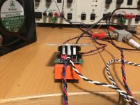
Attached photos of my heatsink on this one - two bits of 12x25x1.5 thick extrusion sandwiched between the main output transistors, with 3mm thick spacers between the drivers and the output transistors, with a 3mmx25mm screw passing through the whole lot. I've got insulators under the screw head and nut, and some thin thermal pads between the output transistors and the inside heatsink.
Firstly I repeated the 5V THD measurement into a 14Ω (3 x 4.7Ω 3W resistors). My result is 0.0010%, compared to 0.0015% at 8Ω and 0.00014% at 47Ω. There's a very approximately linear relationship between THD and load resistance.
Varying supply voltage does absolutely nothing. I ran the amp at +18/-12 and +12/-18 and got 0.0011% (5V into 14Ω) in each case.
The transistor matching idea is a very good one - if one side is better matched than the other then there would be better current sharing pulling one way than the other. I'll build a fixture to match transistors and give it a go.
I'm also thinking that simply throwing more transistors at the problem would yield results, as the impedance that each stage sees is then reduced.
Attached photos of my heatsink on this one - two bits of 12x25x1.5 thick extrusion sandwiched between the main output transistors, with 3mm thick spacers between the drivers and the output transistors, with a 3mmx25mm screw passing through the whole lot. I've got insulators under the screw head and nut, and some thin thermal pads between the output transistors and the inside heatsink.
Attachments
Last edited:
- Home
- Amplifiers
- Solid State
- Cascading diamond buffers - a cheap low THD 10W amp with TIP41C