1/ the volume of a TL is defined by its length & cross-section, rarely as a single number.
2/ TL is not a variant of a BR*. Martin King clearly showed this in one of his papers.
* A BR will transition into an ML-TL as one of the dimensions becomes much larger than the other 2.
dave
2/ TL is not a variant of a BR*. Martin King clearly showed this in one of his papers.
* A BR will transition into an ML-TL as one of the dimensions becomes much larger than the other 2.
dave
thanks Scottmoose for staying involved. I didn't make myself clear on both questions:
1. I realize there are not separate chambers in a T-line but the CSA behind the speaker needs to be a certain minimum depth (affecting volume) which then effects the closed end top CSA and then the terminus.
No it doesn't. You seem to have missed the entire point that GM and I have been making. A QW box has a net bulk, the amount of which determines the lower corner frequencies. If the bulk is smaller than the optimum for a given tuning frequency (set by the acoustical length of the line & hopefully what the driver is actually capable of), gain is reduced. CSA at different points is simply a consequence of cabinet volume and the type / taper of the line.
As Dave notes, a BR is not the same as a TL or QW enclosure, although since they are both vented to the room they do share at a basic level some properties.
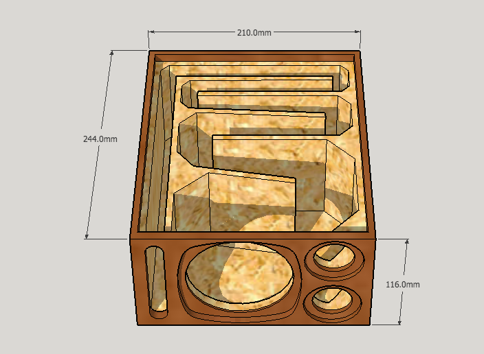
Of the three boxes pictured: frankly none. The first is simply unnecessary; a BR with an overcomplicated vent that provides no advantages I can think of that could not be provided by a simpler alternative. The second is a conventional enough, but not very good, pipe. The third is a large back-horn about 4 1/2ft tall based, as I recall, on a Lowther box, tuned to about 60Hz - 70Hz and utterly unfit to be shrunk to shoebox size; horns cannot be scaled in that way.
Martin King's various TL papers give you good formulas for volume & length for different tapers; you may need to reconvert back since he's worked the equations to provide cross sections, but that's not difficult. Augspurger's papers provide net volumes as I recall. Alternatively, you can use Small's BR equations to establish different volume requirements for the driver.
Last edited:
Nice design. Did you arrive at this via simulation?
No, I don't think the simulation models for transmission lines are particularly accurate with constrained line csa. Instead I simply scaled my existing noisePlank to suit the Sd of the SB driver, and lengthened the line to push the resonance down.
Reminds me of a compact TL monitor I made that was inspired by a PMC monitor.
That's very cool.
Scottmoose, we are saying the same thing, I think. When you say "No it doesn't" I think I must not be making myself clear. My point: When you have a tapered T-line, and you have a certain CSA behind the speaker and the speaker is 1/3 the way down, then with that CSA and the fraction of 1/3, you can figure the CSA at the closed end and at the terminus, which then, gives you the volume since you already know the length. Isn't that correct? If so, then aren't these the things to do in order either using simulation or prototyping:
1. Deciding the quarterwave length
2. Decide the type of T-line
3. Decide the taper ratio, if any taper is wanted
4. Then comes the volume question that we are discussing: determine the CSA/Vol behind the speaker. If you don't do that, then the depth might be too small to install the speaker.
5. Once you get the depth needed which is determined by where you place the speaker in the line, then decide the width of the T-line so the beginning CSA and the terminus CSA work out to the total volume. If the width is too small, then the T-line's volume will suppress the lowest bass frequencies.
I also, to make myself clear, did not suggest that a T-Line is the same as a BR but only as a variant of it as they share some of the same properties. If fact, a T-line can even be made to closely resemble a poor sealed enclosure if you stuff it to much.
As far as the three enclosures - Thanks for your thoughts. Let me see if these make sense:
1st one (post 78) =It is complicated but as well as the other two, it has a smoother "tline" than a box with 45 or 90 degree angles. So if you are saying, that doesn't make a difference than great, because I won't spend the extra time with it because building a box with 45 and 90 degree panels will be easier. So are you saying that, I hope so.
2nd and 3rd one: as far as sound, is there a difference between a long gated spiral line vs a long gated one fold T-line. If not, I can see some advantages: 1. a more compact square design vs tall might fit better in some rooms. 2. no 45 or 90 degree turns. 3. (2nd one) If you reverse the taper, then the driver can be on the outside (down the line to reduce harmonics and maybe easier building with foamcore. Also, the corners might be at the right places (ie Bose patent) for resonance chambers or used for placing amps and circuits.
Am I far off with my reasoning?
Anyway, thanks Scottmoose for helping me,
scott
Last edited:
Note that the corner deflectors habe been shown to be counter-productive.
I'd love a reference for this. I'm using them to ensure relatively constant impedance on the line. They're not deflectors as they're much smaller than a wavelength at the frequencies that'll be in the line.
See https://www.microwaves101.com/encyclopedias/mitered-bends for the rationale behind mitring bends in transmission lines.
Suzyj, That is neat, I've taken interest in your posts and I'm glad you joined this thread - you have practical experience.
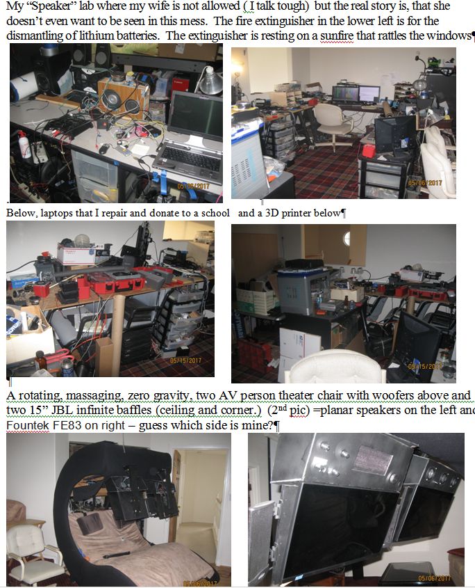
I was 3D printing a potential helix T-Line when my wife came into my speaker "lab" for the first time in a long while. She commented, "what a mess" so here are some older pictures of it - does it look like a mess? Nah
scott
I was 3D printing a potential helix T-Line when my wife came into my speaker "lab" for the first time in a long while. She commented, "what a mess" so here are some older pictures of it - does it look like a mess? Nah
scott
Attachments

Last edited:
I'd love a reference for this.
Work and experiments by Bob Brines, Martin King, Scott Lindgren. The terminus of a TL has to act as a low pass filter. If you leave out the deflectors then the expansion of the line at each bend acts as a low-pass filter, meaning less need of damping and thus more of the fundmental getting thru.
dave
Scottmoose, we are saying the same thing, I think. When you say "No it doesn't" I think I must not be making myself clear. My point: When you have a tapered T-line, and you have a certain CSA behind the speaker and the speaker is 1/3 the way down, then with that CSA and the fraction of 1/3, you can figure the CSA at the closed end and at the terminus, which then, gives you the volume since you already know the length. Isn't that correct?
Not really. You choose a start CSA and an CSA (times the length = volume). The CSA at the driver Zd is whatever it is.
dave
I must really be missing something because I don't think you can have a starting CSA at the "top" of a T-Line without figuring how far down the speaker is in the line. Why am I hung up on this. OK, let me give an example to clarify my thoughts: lets say you start at the top of a 50 inch tapered 10 to 1 t-line and you decide you want it to have a width of 5 inches and a depth of 5 inches (at the top) = CSA=25 and the terminus will equal 2.5. Now if the speaker is 4" deep and you place it at the top of the T-line, then no problem. But if you build the enclosure and then try to place the speaker 1/3 of the way down, it won't fit the depth (the depth is the one being tapered) and will be sticking out the front. I guess if you want to keep the depth the same then you would have to taper a side but if you do that, you still have the same problem trying to place a 4" speaker, 1/3 of the way down.
Now, at the risk of being completely stupid, where am I going wrong with this thinking?
scott
Now, at the risk of being completely stupid, where am I going wrong with this thinking?
scott
The appropriate Zd depends on the line taper. You figure out how big the CSAs are by doing sims.
dave
dave
That makes sense based on if the sims ask the speaker depth and where the speaker is placed on the line - correct? I think we are both thinking the same thing based on your quote "The CSA at the driver Zd is whatever it is." I'm just thinking that you better find that out first the CSA behind the speaker then extrapolate the beginning CSA in a tapered line.
By the way, how do I show a quote in a box like you did. I clicked on "Quote message in reply?" but nothing.
thanks
By the way, how do I show a quote in a box like you did. I clicked on "Quote message in reply?" but nothing.
thanks
Speaker depth?
You decide on a lime geometry and run a sim. Change it in one direction and do another sim… did it get better? Try it again. If it got worse try the other direction.
Click the Quote button.
dave
You decide on a lime geometry and run a sim. Change it in one direction and do another sim… did it get better? Try it again. If it got worse try the other direction.
Click the Quote button.
dave
I think the OP is saying that the driver has to fit into the line where it is positioned. Very basic "how to" stuff that is not stupid, though it is simple. The need to disregard Sd has been overstated, since it is a component of vas. My TL boxes in the 80s had 2x Sd around the driver because that's how much room the basket and magnet structure needed to fit into the box. Give him a break, dear experts. And just build something, OP. Then another two or ten. XRK has shown the way with foam core.
Phivates, you are right, that is what I'm saying - thanks for clarifying. Not sure what OP stands for but I assume that is me. I do agree that building boxes and learning from each build is worthwhile. I have built over 30 and have more drivers sitting around than my age and currently/have refurbished over 200 laptops that are being donated to a school. I have four speaker projects going on now - an adjustable T-line enclosure that will adjust the position of the speaker, the taper and the line length. A concentric tube that converts into a TL, sealed, BR or bandpass by inserting different sections. A audio/video Bluetooth 5.1 portable boombox using a 3d printed helix as a port and a echo DOT 2.1 audio/video lamp. It is a fantastic hobby and I enjoy it.
I was just hoping that I could get a bunch of experts together to coordinate on selecting the best 3 or 4" speaker under $25 with an innovated compact enclosure that I could document all the "considerations, decisions, steps, and designs" and publish it back into this forum but this has been harder and more time consuming than herding cats. So you and Xrk971 are correct about just go ahead and build something.
Thanks for all the comments,
scott
How can a 5.1 system be made portable ? The speakers need to be around the listener...I guess...😕A audio/video Bluetooth 5.1 portable boombox using a 3d printed helix as a port
There is a small pc laptop that attaches to the Home Depot Milwaukee case and it connects to a USB DAC (about 30$) which uses a great piece of PEQ software called Peace. Each channel can have it's own EQ. The surround signal is then sent to two Bluetooth transmitters attached to the USB Dac. Then any nice small portable Bluetooth speakers can be bought. However, I'm making my own with Fountex Fe83 3" in an ported Orb with battery's. You will see it on youtube one day. The .1 of the 5.1 system is a separate Home Depot Milwaukee case that is the sub woofer (if you can call a 12x4x16 box with a 4" tang band 45 Fs a sub.)
Oh dear. You have an affliction known as DIYA and your wife can't stop it. 🙂
Actually, my lab is messier - imagine building 3 amplifier projects simultaneously with speakers. The cleanup happens when one knows SWMBO is about to visit the lab. 😀
Scaling by Sd may not have any mathematical basis as far as the governing equations are concerned, but it does provide a very practical means to get in the right ball park. From a practical standpoint, it will at least allow your box or TL channel to physically accommodate the driver frame and magnet - as Phivates stated above. Also, vents or TL terminus should be no smaller than about 0.33x Sd if you want to avoid chuffing at high SPLs (this is for big higher power speakers). Before I knew how to model and simulate, I scaled things and sometimes it worked quite well. I was always impressed with Planet10 and Scottmoose's FH3, so I scaled it to fit a 3.5in driver. They told me of course that scaling by Sd has no relation to anything. But the resulting speaker sounded pretty good. Years later, they released plans for an FH3 mini (that could be used with FF85WK, and perhaps even a TC9FD) that basically had the exact dimensions of my scaled down homage to their full size FH3. So, for someone starting out in foamcore where investment of time and materials to make something is minimal - and you want to learn and hear different types of speakers. Scaling will get you somewhere close many times. But ideally - scale by Vas if drivers have similar Qts and adjust box width and depth as needed to accommodate driver basket and box volume.
Here is my homage to the FH3 but for a TC9FD and with curvy wings.
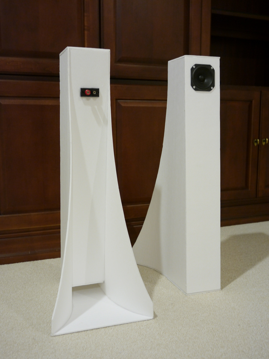
Here is my homage to the FH3 but for a TC9FD and with curvy wings.
Last edited:
Well, if that's your intention, you'll succeed 😛Then any nice small portable Bluetooth speakers can be bought.
Just by changing the speakers ( from 0.50 $ to 20 $ is a big step ! ) and separating the electronics from the cabs.
In 2nd analysys, it'll reveal the ( lo 😀) quality of the stages before the speakers
😱
- Status
- Not open for further replies.
- Home
- Loudspeakers
- Full Range
- Calling all T-Line experts – Designing a 40 Hz compact enclosure