Built the test cabinet today. Don't have enough damping material to fill it, so need to order some.
Initally was going to rerun the mathcad worksheet without any stuffing, and do a comparision with measurements ( expect it to be peaky at the antinodes) to gain confidence and tune the port ( put an oversize slot in the back - to which i have attached a plate which in turn has a 5" adjustable port in it.)
This brings me to the question, where do i start tuning the actual cabs?
Is it a TL or a BR - different damping strategies, on a QW i lined the passage with damping felt and then lightly stuffed at node points with wool- same approach maybe?
Attached is a simulation and the measured response for the MLTL with the 414Z in with only thin felt bonded to the internal panels. What concerns me is i seem to be getting a number of modes below 100 Hz which aren't simulated. Got some light stuffing material today - should i stuff the whole line or only certain parts and if so where?
http://i1227.photobucket.com/albums/ee439/vinylnvalves/mltlundamped_zps86fe6ec4.png
http://i1227.photobucket.com/albums/ee439/vinylnvalves/mltlundamped_zps86fe6ec4.png
The parameters used were for the specific drivers however, when comparing with those GM had originally simulated the MLTL with the variations in the predictions were small. Looking at that stuffing thread, it suggests what i was assuming/thinging. I tried stuffing the top 1/3 of the cabinet, the outcome of this was to increase the magnitude of the peak @ 50hz, the opposite to what i was expecting. All i can conclude from this is the stuffing shortened the effective length, moving the response.
Could these be cabinet responses - unlikely when i have used 30mm particle board, but may add some weights onto of the cabinet and see what happens.
Could these be cabinet responses - unlikely when i have used 30mm particle board, but may add some weights onto of the cabinet and see what happens.
Can remeasure tommorrow. I have some stuffing now, only 2 kg of "soft toy filling".
The measurements were made about 1m infront of the driver. Measured in workshop which is 8m x4m with the speaker in the middle and the door open. It has a hard floor, looking at the room sim in MJK's spreadsheet i can see the response rising above 300hz, its the peaks and troughs below that that i cannot understand.
The measurements were made about 1m infront of the driver. Measured in workshop which is 8m x4m with the speaker in the middle and the door open. It has a hard floor, looking at the room sim in MJK's spreadsheet i can see the response rising above 300hz, its the peaks and troughs below that that i cannot understand.
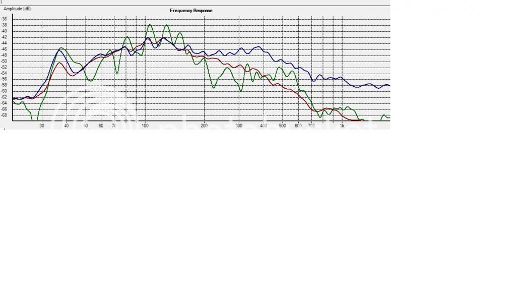
remeasured as suggested - near field (mic 300mm from driver). The results suprised me, i filled the line with the 2kg of stuffing, so less than 0.5 ib/ft^3, this flattened the > 100hz response as expected. The effects of measurement position can be seen in the attached FR plot. The 3 traces show 300mm, 900mm and 1500mm mic positions. http://i1227.photobucket.com/albums/ee439/vinylnvalves/mltldampedresponse_zpsc1a8ae58.jpg
Looking at MLK's mathcad room effects predictor, its clear that the room effects are as significant as tuning the cabinet.
I will over the weekend move the test cabinet into my listening room and see if the MLTL sound/signature appeals to me.
Looking at MLK's mathcad room effects predictor, its clear that the room effects are as significant as tuning the cabinet.
I will over the weekend move the test cabinet into my listening room and see if the MLTL sound/signature appeals to me.
Moved the test cabinet into the listening room, yesterday. Carried out further measurements to see how much less reactive this room is than the workshop. I carried out listening position and near field measurements. I also introduced some series resistance in the form of a inductor to see the effects of this on Qts. I will let you guess which trace is which.
Also as requested i did a real near field ( could only get mic within 6" of driver due to stand) and a port measurement.
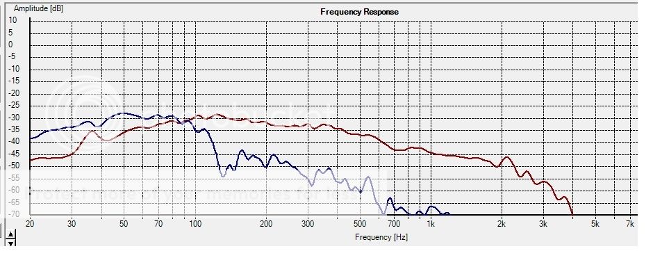
I tried out tackle the ~35hz peak - by changing the port length, without any success, almost suggesting that its not doing its job, but don't know why - any explaination, suggestions on what i should do next.
By the way i listened to system with the MLTL in place. The bass is tighter (drier) than the Onkens - quite like it, seems to go lower but that could be the 35Hz resonance!!
Nobody got any advice on what i should do next ?
From my uneducated point of view it looks as if i could sum the post and driver outputs - ie have the port on the front of the cabinet, i would get a different low end response. As i want to push the cabinets towards the wall/corners a front post maybe sensible. I tried moving the port location in MJK's room sim, from the back to the front of the cabinet, it didn't seem to predict that bigger difference.
From my uneducated point of view it looks as if i could sum the post and driver outputs - ie have the port on the front of the cabinet, i would get a different low end response. As i want to push the cabinets towards the wall/corners a front post maybe sensible. I tried moving the port location in MJK's room sim, from the back to the front of the cabinet, it didn't seem to predict that bigger difference.
Well, summing the port and driver measurements would get you new nice looking graph, but I would go for averaging few 1/3 octave RTA measurements of the 1m^2 around listening spot. I believe this would give you more precise look at the bass response of your box than nf measurements summation.
Regarding the 35Hz peak - it wasn't there in your first nf graph (post #48)?
Regarding the 35Hz peak - it wasn't there in your first nf graph (post #48)?
With regard to the peak @ 35 Hz, it was at 40 Hz before when in the workshop. Changes when moved to listening room, changed amp - was using a 20 watt T amp - now using a 300watt one with better damping. The cabinet is placed 400mm away from a wall, was a good 1.5m from any obstruction in the garage.
I did some far field measurments they were not any better than those i took in the workshop, they follow the trend of the FR trace in post 51 a little bit more peaky than the green one.
I did some far field measurments they were not any better than those i took in the workshop, they follow the trend of the FR trace in post 51 a little bit more peaky than the green one.
I've lost track, I did some sims, but not sure what you built. Regardless, no MLTL I've done/seen response measurements of had any peaking at Fb like one can get with a reflex, which isn't surprising since the high aspect ratio cab is over-damping the vent.
If the measurements are accurate, it appears that the vent isn't working at all in the driver's BW, i.e. the peak appears to be around the driver's Fs, indicating an air leak.
Something's not right though as an inductor won't 'ripple' a driver's response. Indeed, the way it's tracking the response in the 100-200 Hz BW makes it seem like this is where the cab is tuned.
GM
Thanks for that. I tried loading it, without success, issues loading the MS framework needed to run it. This could be why my copy of mathcad doesn't work. May ask one of the offspring if i can borrow one of their more upto date laptops (that i bought anyway) and see if it works on that.
Requires .Net 4
GM I built a test cabinet using the sheet material i had in the shop, close to your simulation, running my own sim for the parameters i ended up with.
Differences as follows Lenght= 63" instead of 61"
SL and So were 200 sq in not 240 sq in.
Port and driver positions as specified. As i think i mentioned the post position can be located between 46" and 52" ( have played with this - did not seem sensitive)
Differences as follows Lenght= 63" instead of 61"
SL and So were 200 sq in not 240 sq in.
Port and driver positions as specified. As i think i mentioned the post position can be located between 46" and 52" ( have played with this - did not seem sensitive)
My experience with expanding MLTL designs is that it requires something around one third more in length to get the same line tuning as straight. 61" seems short. Agreed, line tuning appears to peak around ~130Hz. Could be an air leak, doesn't take much. Haven't sim'ed this driver in particular, just saying ")
The 35Hz peak is most likely your primary room resonance, smaller primary (length) in your work shop yields around 40. Only fix is placement or use of multiple woofers. Tuning the box to fix would not help with this. REW (Room Equalization Wizard) has a (simple) room modeler as part of it's repertiore. A visual aid in placement and resonance issues. Comes in handy and is free
The 35Hz peak is most likely your primary room resonance, smaller primary (length) in your work shop yields around 40. Only fix is placement or use of multiple woofers. Tuning the box to fix would not help with this. REW (Room Equalization Wizard) has a (simple) room modeler as part of it's repertiore. A visual aid in placement and resonance issues. Comes in handy and is free
- Status
- This old topic is closed. If you want to reopen this topic, contact a moderator using the "Report Post" button.
- Home
- Loudspeakers
- Multi-Way
- Cabinet Design for Altec 414z's