GM
AOT = adjust on test
" Well, the MLTL is a simple to design/build/tweak, higher sound quality [SQ] vented alignment, so hard to go wrong with it IF it meets the needs of the app" Your statement corcerns me, what is the downside of the MLTL ? ( My assumption was if the onken works for me then should be similar with better LF, based on your comments.
Just reading into what your saying, i just make the cabinet as big as possible with a TL around 62" and tune the port to get what i want.
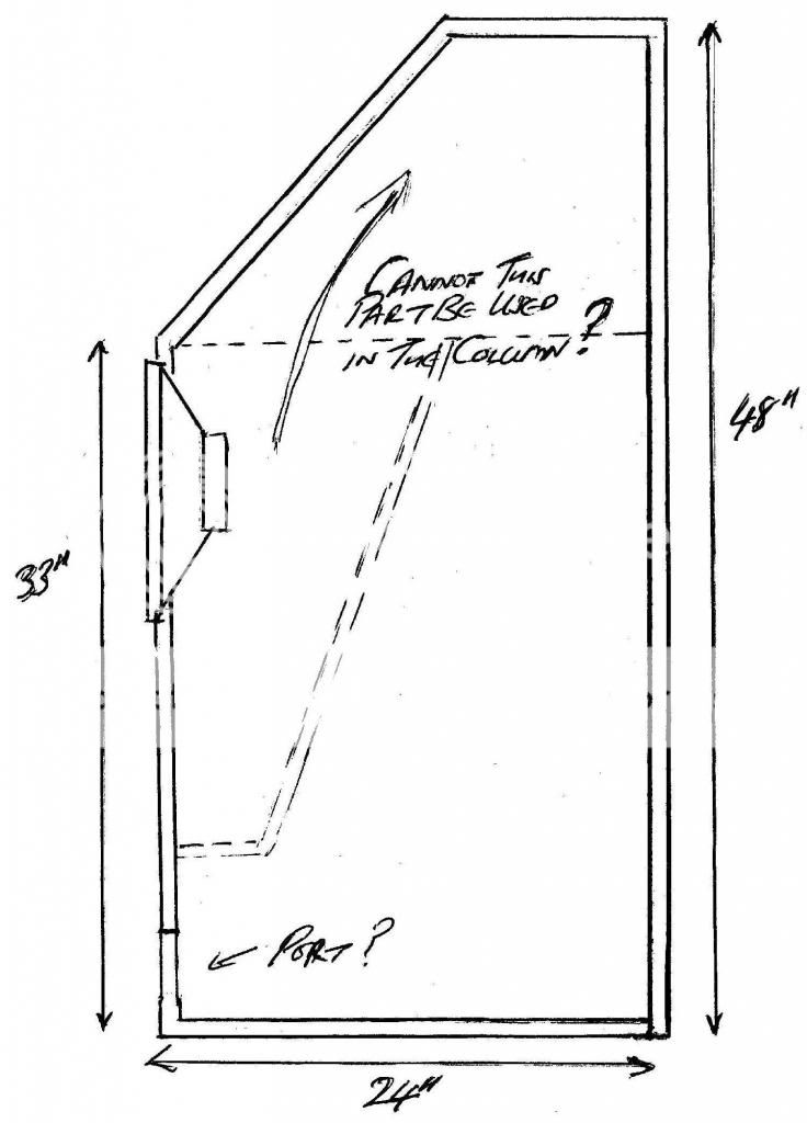
Would it not be possible to use a non rectangular cabinet ...
Whats the issues with expanding MLTL as i have seen a number on the web, and lends itsself better to the cabinet shape i propose.
I need to get MJK software up and running so i can simulate, i assume port location and room effects need to be accounted for?
Have some particle board i was goint to knock up a test cabinet, so i can experiment with port and driver location etc. Can initially make a simple rectangular cabinet to see how the MLTL integrates with the horns, so a good starting point would be appreciated.
I noticed someone putting a Karlson type port on their MLTL i assume that this is not the right thing to do?
On the topic of cleaning the altec surrounds - is a tooth brush to stiff to move the doping around with?
AOT = adjust on test
" Well, the MLTL is a simple to design/build/tweak, higher sound quality [SQ] vented alignment, so hard to go wrong with it IF it meets the needs of the app" Your statement corcerns me, what is the downside of the MLTL ? ( My assumption was if the onken works for me then should be similar with better LF, based on your comments.
Just reading into what your saying, i just make the cabinet as big as possible with a TL around 62" and tune the port to get what i want.
Would it not be possible to use a non rectangular cabinet ...
Whats the issues with expanding MLTL as i have seen a number on the web, and lends itsself better to the cabinet shape i propose.
I need to get MJK software up and running so i can simulate, i assume port location and room effects need to be accounted for?
Have some particle board i was goint to knock up a test cabinet, so i can experiment with port and driver location etc. Can initially make a simple rectangular cabinet to see how the MLTL integrates with the horns, so a good starting point would be appreciated.
I noticed someone putting a Karlson type port on their MLTL i assume that this is not the right thing to do?
On the topic of cleaning the altec surrounds - is a tooth brush to stiff to move the doping around with?
That was a figure if speech, obviously if space wasn't an issue, i would probably be considering a front loaded horn. I am wondering if something like the Edgar "show horn" may be an alternative to whats being discussed. With my space constraints this would be limited to around 45 hz, assuming i get help from the corners of the room.
GM,
You got cab dimensions on this one. Stilll have a pair of 414's to pair with 806's
I already posted all the pertinent dims except I forgot the vent location, which is
~12.2" up from the back bottom.
GM
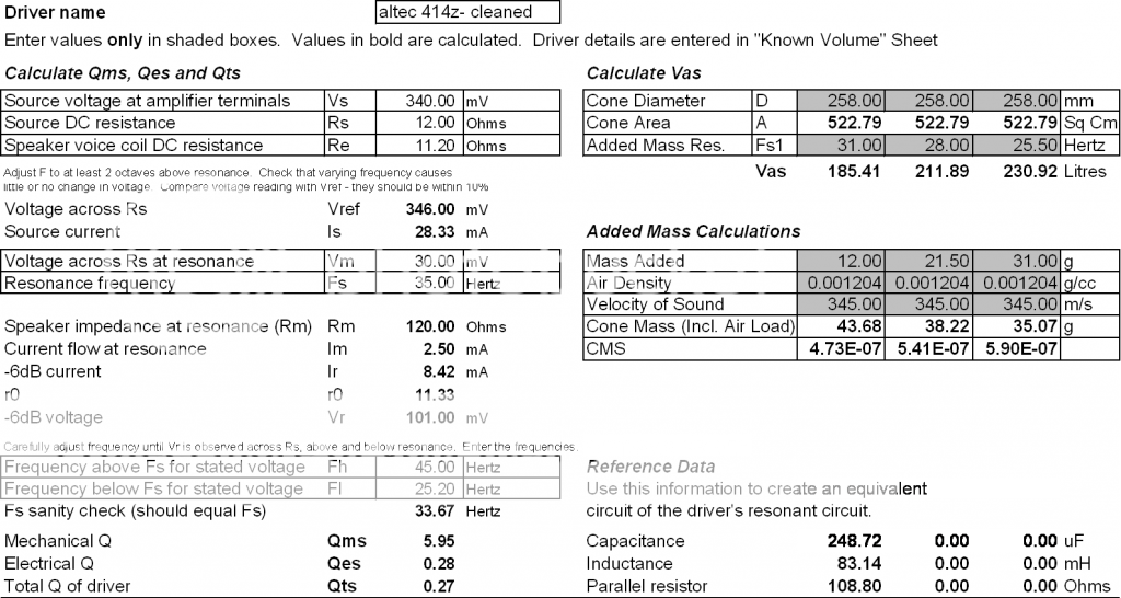
Got around to measuring the 414'z. Using the -6db approach i got the following for one of the drivers
fs=38hz qms=3.0 qes=0.25 and qts=0.23 Vas=160 ltrs Re=11.2 ohms ( the VAS determined this using a closed volume, adding weight method gave me 466 ltrs - quoted Altec spec was 256ltrs so not close with either approach.)
Not as close as i was expecting, but then again they are 47 years old. I may try cleaning the goop off the surround and then remeasure to see what changes.
Long time doing other things, starting to look at the cabinets again. Managed to get the fs down to 35hz by cleaning the surrounds with some MEK (well really redistributing it). Started looking at the MLTL cabinet again for these drivers. Managed to find my account details for MJK's site and software so was going to try replicating GM's simulation in Mathcad, unfortunately my student version of mathcad doesn't seem to load anymore, and don't feel like paying out again for it.
Reason i wanted to simulate it isn't i wanted to second guess GM but was looking at making the cabinet a little taller @ 36" ( better for the TPL) and was going to attempt to work out what i needed to change. I was going to keep Vb the same and adjust the CSA down accordingy for the extra 4" of height.
Initially my throughts are to knock together a simple cabinet from particle board adding the flexibility to move the port location so i can fine tune.
One thing i was musing with is can the Decca corner horn approach of having reasonant cabinet panels to damp the harmonics as suggested by Ralph West be used to minimise internal stuffing used with MLTL's or is this an idea from the 1960's best ignored?
freebie TL software
Tho not as accurate as MJK's speadsheets, Transmission Line v.3.6.1.14 does a nice job. Known to be accurate from ~80-200Hz. Above 200 the resonances are greatly lifted in amplitude and below 80 response is reduced by 6-8dB @20Hz. Take this into consideration and it works quite well.
Here is the diy thread
Thanks for that. I tried loading it, without success, issues loading the MS framework needed to run it. This could be why my copy of mathcad doesn't work. May ask one of the offspring if i can borrow one of their more upto date laptops (that i bought anyway) and see if it works on that.
Greg B's "Karlsonator" might be a decent fit - its only been kludge sim-ed at this point http://img141.imageshack.us/img141/124/karlsonator.png
the regular 15" Karlson would probably sound punchy with a 414
the regular 15" Karlson would probably sound punchy with a 414
Just been measuring the parameters of my drivers post cleaning. I have a query regarding measuring the VAS of the driver. I have found the added weight method most reliable, however it seems to be sensitive to the added weigth, what added weight is most appropiate. Attached is a spreadsheet that highlights my measurements and the effect of added weight
You're welcome!
Well, if Fsa is 31 Hz, then Fs' needs to be at least 31/1.5 = <20.67 Hz and preferably 31/1.56 = <19.87 Hz.
FWIW, Altec's official Sd spec = Vd/Xmax = 11.87"^3/0.15" = ~79.133"^2 = ~510.5364 cm^2, which will affect your measurement, though as Joe D. notes, Vas can be off 25% without audible impact and ~230 L is plenty good enough based on others I have specs on.
GM
OK, to recap to make sure we’re on the same ‘page’ before making any changes:
Posted ~32 Hz Fb sim’s details. Driver specs is an average of many measured + factory published specs, so may, may not be ‘ideal’ for every driver/app as simmed, i.e. strictly a starting point, but the cab should be acoustically large enough to match it to any factory [re]cone driver even when driven with a high output impedance except possibly those with AlNiCo motors that either needs to be drained/remagnetized or was done and for whatever reason didn’t take a full charge.
Unfortunately, re-coners typically do not check them, so recommend offering to pay for having T/S specs measured.
Ferrites should never need recharging unless physically damaged and even then I’ve measured many a small motor’s magnets that actually was stronger after being chipped and/or even split in two in a few cases, which FWIW led to a performance breakthrough by ‘stacking’ high aspect ratio magnetic ‘bars’.
GM
Attachments
![Altec 414 composite specs [default] ~32 Hz MLTL.gif](/community/data/attachments/336/336179-66127f0ab851a4dd2d81cb5d1826f0de.jpg)
Got mathcad working - using model TL_ML_Corner_8_14. I get very similar simulations of the SPL trace to what GM posted for the 5.5" port. Can see that Qtd dominates the response putting in the values for the driver i measured does not seem to change the response much - which suggests a robust point in the design curve. What other things other than the SPL trace should i look at whilst i am having a play, looking at port sizes locations etc.
I read somewhere that for low qts drivers a ratio of 1:10 should be used between So and SL i tried it, improves the lower response but introduces a hump at 30hz, even after recalculating a port to suppress it. I see alot of people use tapered MLTL - whats the advantage, the only one i can see is like in a Decca QW you can lengthen the line as the terminus area is smaller and another fold can be introduced.
I read somewhere that for low qts drivers a ratio of 1:10 should be used between So and SL i tried it, improves the lower response but introduces a hump at 30hz, even after recalculating a port to suppress it. I see alot of people use tapered MLTL - whats the advantage, the only one i can see is like in a Decca QW you can lengthen the line as the terminus area is smaller and another fold can be introduced.
Right, the basic ‘streamlined’ reflex formula is Vb = 20*Vas*Qts^3.3.
Yes, driver, vent location in [ML]TLs can audibly impact its response, ergo the amount of damping required to smooth it out and being ‘old school’, the less the better to keep acoustic efficiency as high as practical.
Well, the way I view it, since a low Qt driver calculates a maximally flat alignment that makes for a relatively small cab with a long vent if tuned to Fs, then morphing it into a TL makes it an inverse tapered one [TQWT], ergo SO will be larger than SL, which typically will be whatever size you want the vent.
AFA ratios to use, MJK came up with some guidelines in his Classic TL Alignment Tables doc, but with no computer software or T/S specs per se to guide me ages ago, I empirically arrived at 10:1, which worked good enough for me in most cases, but up to 20:1 is an option for drivers that allow a small vent [< ~Sd/4].
Conversely, I use [ML]horns for high Qt drivers. Most popular drivers work fine in constant [straight] taper [ML]TLs though, so the default one to sim first.
GM
- Status
- This old topic is closed. If you want to reopen this topic, contact a moderator using the "Report Post" button.
- Home
- Loudspeakers
- Multi-Way
- Cabinet Design for Altec 414z's