Eddy,
great that things are looking up.
Looks like various people here have found the WIKI list for those that want F4 boards from Peter.
I'm not sure what Nelson's intentions are as far as offering boards for sale but if he isn't planning to then this is a very fortunate effort at just the right time.
http://www.diyaudio.com/wiki/index.php?page=FirstWattPCBReissues
Variac said:Eddy,
great that things are looking up.
Looks like various people here have found the WIKI list for those that want F4 boards from Peter.
I'm not sure what Nelson's intentions are as far as offering boards for sale but if he isn't planning to then this is a very fortunate effort at just the right time.
http://www.diyaudio.com/wiki/index.php?page=FirstWattPCBReissues
Thanks Variac!
I didn't know about the F4 boards until you posted the link. I put myself down for 2, and also for 2 PS boards (not sure if I'll need em).
-Olen
So.....
I think I've worked out a nice front end which will accommodate everyone's
needs with regard to this chassis. The all N channel guys will get something,
the complementary Mosfet guys will get something, and even the Bipolar
guys can use their output stages.
With lots of options to keep you busy until the second coming...
So stay tuned.

 No bipolar for me!
 OK, I got some pics:
See Solid State Pictures Thread : http://www.diyaudio.com/forums/showthread.php?s=&threadid=96192&perpage=25&pagenumber=25
Sounds just fine now ... Thanks Nelson, I may have a need for more chassis like these ... How's chances?
See Solid State Pictures Thread : http://www.diyaudio.com/forums/showthread.php?s=&threadid=96192&perpage=25&pagenumber=25
Sounds just fine now ... Thanks Nelson, I may have a need for more chassis like these ... How's chances?
power supply: http://www.diyaudio.com/forums/showthread.php?postid=1674914#post1674914 ... note trany and big caps ... that's all. +/0/- 65 VDC rails into well filtered modules ... PS ripple and crosstalk (on my 'scope) shows up in the ~2 millivolt range on the speaker lugs with signal at output >~ 40 volts ... which I suppose is a voltage ratio better than 2000 to 1, ... loaded left channel verses the "no signal" right channel
I see the transformer and the big caps, I was just wondering where you hid the rest of it.
Is there any issue with mounting the modules over the transformer like that? Does that strong electromagnetic field disturb the signals in any way?
I ask these questions because I'm trying to figure out how I'm going to lay out my burning amp.
Is there any issue with mounting the modules over the transformer like that? Does that strong electromagnetic field disturb the signals in any way?
I ask these questions because I'm trying to figure out how I'm going to lay out my burning amp.
" ... where you hid the rest of it. ..."
Not regulated other than the "brute force" of the caps. The modules each have a combination of plastic and electro caps for added filtering.
" ... Is there any issue with mounting the modules over the transformer like that? ..."
Probably, but I don't see it on the 'scope. Maybe I should look harder.
" ... I'm trying to figure out how I'm going to lay out my burning amp. ..."
If your are following a PassLabs type design, I would seek info / help from that thread. The topography and PS requirements of the PassLabs design are completely different than mine.
Hey guys, my spidey sense is tingling. That means I either drank too much rum or that Papa/amp god/Nelson Pass will be revealing his first Burning Amp design in a couple of weeks!
And we haven't matched our MOSFETs yet! I think that at this point we are looking for someone who has some experience doing it and we will be willing to go where that person is, OR where the equipment is that the person needs.
If no one has the knowlege, then someone needs to try following Nelson's directions and get confident in doing matching as we have a lot of 'em to do!
I'm pretty booked up with diyAudio stuff ATM and can't put in the time to learn. Anyone have the time and equipment , or even better - knowlege?
Mark
To do mass matching that actually works, I have found it useful to make a big clamp of say 1" by 2" aluminum bars, with a bolt per 10" to clamp the mosfets. From there it's simple, just follow the matching pdf Nelson has written. The circuit is simple to breadboard.
Get a respectable meter, Fluke 187 comes to mind. 3 alligator clips, and some nice soft wire in 3 different colours.
Then it's just a matter of writing a number on all the mosfets, and make a list where you write down the measured results.
Last you can put all the numbers in a spreadsheet, and easily look through the whole shebang, to find the matching fets.
Magura
Matching
I run the 15volts across 55 ohms using 5 3 watt resistors, using Papa's older article as a guide. The voltage doesn't change if I leave it there for a few seconds, and it's doesn't get too hot.
I just leave it oon a piece of wood.
I am not sure if there is a better method to do it.
I certainly have a few HP power supplies to work with.
Re: Matching
One important point is to match the transistors at the a current close what they will be exposed to in terms of bias in the finished amp. If the transistors don't get hot, you are not doing it correctly.
I'm using steenoe recipe: Calculate R so that you get ~1amp - put in the device, start the clock when you reach 20sec press "hold" on your DMM - now write the number on the chip and go on. It is crucial to be exact with the timing since the device will wander several millivolts each second.
It is also a good idea to warm up the rig with other devices that you are not going to match.
Tea-Bag said:I run the 15volts across 55 ohms using 5 3 watt resistors, using Papa's older article as a guide. The voltage doesn't change if I leave it there for a few seconds, and it's doesn't get too hot.
I just leave it oon a piece of wood.
I am not sure if there is a better method to do it.
I certainly have a few HP power supplies to work with.
One important point is to match the transistors at the a current close what they will be exposed to in terms of bias in the finished amp. If the transistors don't get hot, you are not doing it correctly.
I'm using steenoe recipe: Calculate R so that you get ~1amp - put in the device, start the clock when you reach 20sec press "hold" on your DMM - now write the number on the chip and go on. It is crucial to be exact with the timing since the device will wander several millivolts each second.
It is also a good idea to warm up the rig with other devices that you are not going to match.
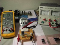
Sockets are very convenient for matching, indeed. Here is a pic of a simple, matching rig with sockets. I made it to accomodate both P-channel and N-channel TO247 devices, along with To220's. Just to make it more flexible in use. For simple VGS testing this will do fine, if done as cviller outlined above. The mosfet on the pic is being measured at 15v 0.5A, as needed for this occasion. Just trim the resistor value, as needed. I use 2 pcs 10 watt resistors in // for testing at 1A. The most important part, after the rig has reached a stable temp, is to go along at a steady pace, so every FET is measured the excact same way.
I dont turn the power off the supply, between FET's, and never had an accident on that account, yet.
The schematic is in the Zen variations, part 3. Active supply regulation.
I dont turn the power off the supply, between FET's, and never had an accident on that account, yet.
The schematic is in the Zen variations, part 3. Active supply regulation.
Attachments
Those of you who received the amps at BAF with all N channel
output devices can start getting ready. BA #1 will launch as soon
as DIYAudio is ready to post it, probably in about 10 days.
It's a single-ended Class A design coming in at around 25w/ch with
local feedback only. It will apply to both the large (6 deep) and small
(4 deep) output stages, and will have balanced and single-ended inputs.
It's a very nice amplifier.
The secondary rails will be in the 18 to 25 v region, and most of you
will be tapping your transformer primaries at 240V to get this.
Those of you with the shorter amps and only the two ps caps should
consider another pair of caps mounted somewhere toward the front
of the amp to get lower noise.
I am working up a pc board design for the front end and boards will
be made available, if not through DIYAudio then through PassDIY.
Those of you with complementary output stages (N and P) will get
a similar but different design shortly.
Most likely this is only the first of a series of designs which employ
the same hardware. In all likelihood you will be able to explore
al of them without too much effort.
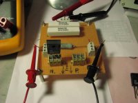
A closer shot of the test board. It has 2 voltage input's 1 going to the 10 watters, the other to a 5 watter, used for the To220 devices, which are matched at a lot lower current.
I have found it a really handy little gadget, making matching life a lot easier.
I have found it a really handy little gadget, making matching life a lot easier.
Attachments
- Status
- This old topic is closed. If you want to reopen this topic, contact a moderator using the "Report Post" button.
- Home
- Amplifiers
- Pass Labs
- Burning Amps