Hi John,
Thanks, as ever, for your guidance and advice.
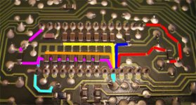
I have coloured the CD630 pcb with the same colour scheme that you have used.
I think the CD630 would benefit from the following mods :-
1) Cutting the tracks joining the L and R active divider returns.
2) the +5V (red) would be better with a shorter return to pin 5 by moving the cap onto the round pad below the pin and then straight down to join back to the existing red track.
3) The -15V (purple) could be re-routed straight down from pin 15 with the cap joining the ladder at the top left corner and then down and across to the right (having separated off the L and R returns).
An alternative perhaps would to relocate the SMT caps so that one end is directly on the DAC pin and then join it to the existing pin side pad and join them together to make a new return path. The -15V could then use the R return path instead.
Jon
Thanks, as ever, for your guidance and advice.
I have coloured the CD630 pcb with the same colour scheme that you have used.
I think the CD630 would benefit from the following mods :-
1) Cutting the tracks joining the L and R active divider returns.
2) the +5V (red) would be better with a shorter return to pin 5 by moving the cap onto the round pad below the pin and then straight down to join back to the existing red track.
3) The -15V (purple) could be re-routed straight down from pin 15 with the cap joining the ladder at the top left corner and then down and across to the right (having separated off the L and R returns).
An alternative perhaps would to relocate the SMT caps so that one end is directly on the DAC pin and then join it to the existing pin side pad and join them together to make a new return path. The -15V could then use the R return path instead.
Jon
Attachments
I'd like ecdesigns, galeb and maybe even studiostevus to tell us how wonderful it all sounds and then what happens to the sound when they make another big step in technical performance..
Am I being too simple here ?
Hi,
Technical questions are not simple, as human being is not simple.
I can talk respect to the clock changes mainly, and in my CD player, a Philips 360. Improving the phase noise of the oscillator, (after having bypassed the SAA7000 to avoid the oversampler and digital filter, and remaking the clock distribution pcb tracks), the first thing you hear is a better channel separation, pushing it to it's limits, and believe me, 98db here are a lot. Comparing it with a Heavily modified (by me) Mark Levinson N 360S+Wadia transport+Transparent digital cable, this last one opens the image a little more, and taking into account that the Levinson has 4xPCM1704K, this Philips CD is a winner.
The music is more real, more relaxed, not fatiguing. I've been hearing this Philips player with a Senheisser HD800, drived with a project head box (heavily modified by me, again) a lot of hours, and being the HD800 a little bit analitical, it surprises me the convenience of listening. I can hear hours and hours.
Respect to the signal treatment, the first thing I hear is SILENCE, an incredible level of silence. Bad recordings with a lot of noise can be heared with a lot of noise, but the good ones, wow, I can hear a noise floor so low, that it remains me a good turntable. The detail level is astounding, very very detailed, no grain, a lot of "microplancton"....
And finally, the audio output stage. It's very important to avoid the capacitors, as we all know. Anyway, Aikido stage with 6N2P and 6H23 with Vcap (teflon, a total of 10uf at least), sounds very very good and detailed, very fast, good bass, and sweet voices...
Hope this little explanation helps you. I know you want to go to the final solution, because you can't wait more.....
http://www.diyaudio.com/forums/digi...e-nos-dac-using-tda1541a-366.html#post2549175Krokotam,
You'll find the mk7 schematics in post 36**, I'm assuming that's what you're after.
The stars are in the last two digits to make you READ. Which I'm assuming you have not done.
Happy reading.
You'll find the mk7 schematics in post 36**, I'm assuming that's what you're after.
The stars are in the last two digits to make you READ. Which I'm assuming you have not done.
Happy reading.
Hi Krokotam_,
This thread documents a DAC design process. Multiple schematics were puplished as improvements were made to the design.
The latest design that has proven its performance for quite some time now is the TDA1541A MK7 DAC. The power supply for the MK7 DAC is not final yet, the current prototype with common-mode suppressors is able to equal battery power supply performance while running on a highly polluted mains voltage. Interference / ripple suppression of this prototype equals approx. 280 million on each of the 4 isolated output voltages. Other version is being developed offering interference / ripple suppression factor of 163 billion. I hope to get some marginal improvements in relaxation in the sound using this concept.
The final volume control is the binary stepped shunt volume control, based on non-inductive wire wound resistors for lowest noise and maximum resolution. It uses selected steps from a total of 256 steps to approximate logarithmic response using only 8 bits / switchable resistors. Multiple selected resistors are in parallel, there is only 1 fixed series resistor that is soldered directly between input and output.
The power amplifiers are Circlotron monoblocks with total of 4 MOSFETs / monoblock and passive common mode filters on all power supplies.
With the current setup, the audio set gets "out of the way" leaving only the music. The set is also able to get the very best out of each CD, regardless of CD recording quality. So instead of only enjoying few high quality recordings, I can now enjoy all my CDs. This is probably a result of systematic interference reduction, leaving only the information stored on the CD.
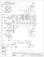
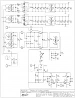
I attached latest MK7 and Circlotron schematics for convenience. Note that all 1uF decoupling caps are now soldered directly to the TDA1541A pins (photograph published few posts ago) and that L and R output pins are also soldered directly to the PCB.
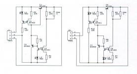
The DRN05, DRP05, and DRN15 are discrete voltage regulators (attached schematics). R4 and R9 set the output voltage.
The only thing that's not on the schematics is the variable reference voltage for DC-coupled DAC output. It consists of a 1K trimmer connected between +5V and GND with a 1uF SMD film cap between wiper and GND. One of these circuits is required for each channel. The pot is adjusted until there is zero volts DC between wiper and DAC output. The wipers serve as "GND" reference for connected equipment.
I really can'¨t find any scheme in this 382 pages theme , can someone help me ? I believe that this should be the first thing you need to see in this thread !
This thread documents a DAC design process. Multiple schematics were puplished as improvements were made to the design.
The latest design that has proven its performance for quite some time now is the TDA1541A MK7 DAC. The power supply for the MK7 DAC is not final yet, the current prototype with common-mode suppressors is able to equal battery power supply performance while running on a highly polluted mains voltage. Interference / ripple suppression of this prototype equals approx. 280 million on each of the 4 isolated output voltages. Other version is being developed offering interference / ripple suppression factor of 163 billion. I hope to get some marginal improvements in relaxation in the sound using this concept.
The final volume control is the binary stepped shunt volume control, based on non-inductive wire wound resistors for lowest noise and maximum resolution. It uses selected steps from a total of 256 steps to approximate logarithmic response using only 8 bits / switchable resistors. Multiple selected resistors are in parallel, there is only 1 fixed series resistor that is soldered directly between input and output.
The power amplifiers are Circlotron monoblocks with total of 4 MOSFETs / monoblock and passive common mode filters on all power supplies.
With the current setup, the audio set gets "out of the way" leaving only the music. The set is also able to get the very best out of each CD, regardless of CD recording quality. So instead of only enjoying few high quality recordings, I can now enjoy all my CDs. This is probably a result of systematic interference reduction, leaving only the information stored on the CD.
I attached latest MK7 and Circlotron schematics for convenience. Note that all 1uF decoupling caps are now soldered directly to the TDA1541A pins (photograph published few posts ago) and that L and R output pins are also soldered directly to the PCB.
The DRN05, DRP05, and DRN15 are discrete voltage regulators (attached schematics). R4 and R9 set the output voltage.
The only thing that's not on the schematics is the variable reference voltage for DC-coupled DAC output. It consists of a 1K trimmer connected between +5V and GND with a 1uF SMD film cap between wiper and GND. One of these circuits is required for each channel. The pot is adjusted until there is zero volts DC between wiper and DAC output. The wipers serve as "GND" reference for connected equipment.
Attachments
Hi Krokotam_,
This thread documents a DAC design process. Multiple schematics were puplished as improvements were made to the design.
The latest design that has proven its performance for quite some time now is the TDA1541A MK7 DAC. The power supply for the MK7 DAC is not final yet, the current prototype with common-mode suppressors is able to equal battery power supply performance while running on a highly polluted mains voltage. Interference / ripple suppression of this prototype equals approx. 280 million on each of the 4 isolated output voltages. Other version is being developed offering interference / ripple suppression factor of 163 billion. I hope to get some marginal improvements in relaxation in the sound using this concept.
The final volume control is the binary stepped shunt volume control, based on non-inductive wire wound resistors for lowest noise and maximum resolution. It uses selected steps from a total of 256 steps to approximate logarithmic response using only 8 bits / switchable resistors. Multiple selected resistors are in parallel, there is only 1 fixed series resistor that is soldered directly between input and output.
The power amplifiers are Circlotron monoblocks with total of 4 MOSFETs / monoblock and passive common mode filters on all power supplies.
With the current setup, the audio set gets "out of the way" leaving only the music. The set is also able to get the very best out of each CD, regardless of CD recording quality. So instead of only enjoying few high quality recordings, I can now enjoy all my CDs. This is probably a result of systematic interference reduction, leaving only the information stored on the CD.
I attached latest MK7 and Circlotron schematics for convenience. Note that all 1uF decoupling caps are now soldered directly to the TDA1541A pins (photograph published few posts ago) and that L and R output pins are also soldered directly to the PCB.
The DRN05, DRP05, and DRN15 are discrete voltage regulators (attached schematics). R4 and R9 set the output voltage.
The only thing that's not on the schematics is the variable reference voltage for DC-coupled DAC output. It consists of a 1K trimmer connected between +5V and GND with a 1uF SMD film cap between wiper and GND. One of these circuits is required for each channel. The pot is adjusted until there is zero volts DC between wiper and DAC output. The wipers serve as "GND" reference for connected equipment.
GREAT ! Now i have to look at it for some time

THANKS FOR SHARING THIS !
Simple Note : 1uF SMD film cap between wiper and GND
Try tantalum caps in there
Last edited:
Hi Alexiss,
I have been very busy over the past months, extending my work space with 70 square meters. Building is almost completed (still need to complete interior work). During this time audio developments had to be put on halt.
Recently I continued development of the MK7 power supply. I am now testing a common-mode ripple suppressor / voltage regulator for the MK7. This new supply uses a common-mode ripple suppressor (2 Darlingtons), followed by a common-mode buffered / filtered zener (2 Darlingtons). Output voltages are +5V, -5V, and -15V, so the MK7 on-board regulators can be removed. I still have to perform critical listening tests / comparisons to make sure the new power supply offers equal or improved performance over the common mode ripple suppressor / discrete regulator configuration.
Schematics: Orcad SDTIII
PCB: Orcad PCBII
I use custom component libraries that I developed over the past 20 years.
The programs run under DOS with less than 640 kilobytes of RAM memory available for CAD program, libraries, drivers and design.
Thanx again for keeping this thread alive and kickin!
I have been very busy over the past months, extending my work space with 70 square meters. Building is almost completed (still need to complete interior work). During this time audio developments had to be put on halt.
Recently I continued development of the MK7 power supply. I am now testing a common-mode ripple suppressor / voltage regulator for the MK7. This new supply uses a common-mode ripple suppressor (2 Darlingtons), followed by a common-mode buffered / filtered zener (2 Darlingtons). Output voltages are +5V, -5V, and -15V, so the MK7 on-board regulators can be removed. I still have to perform critical listening tests / comparisons to make sure the new power supply offers equal or improved performance over the common mode ripple suppressor / discrete regulator configuration.
Just wondering: what is the schematics software you use to draw your schematics and make your pcbs?
Schematics: Orcad SDTIII
PCB: Orcad PCBII
I use custom component libraries that I developed over the past 20 years.
The programs run under DOS with less than 640 kilobytes of RAM memory available for CAD program, libraries, drivers and design.
Hi Krokotam_,
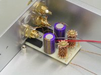
My mistake, I use 470uF Oscon caps here (attached picture). The DC bias circuit contains of a 1K (bulk metal foil) multiturn trimmer, a 470uF / 16V Oscon decoupling cap and a Honeycomb Mobius loop for each channel.
The 1uF SMD film caps are used on the wipers of the DC-offset pot on the MK7 board that is used for achieving 0V DC on the DAC chip output pins.
Simple Note : 1uF SMD film cap between wiper and GND
Try tantalum caps in there
My mistake, I use 470uF Oscon caps here (attached picture). The DC bias circuit contains of a 1K (bulk metal foil) multiturn trimmer, a 470uF / 16V Oscon decoupling cap and a Honeycomb Mobius loop for each channel.
The 1uF SMD film caps are used on the wipers of the DC-offset pot on the MK7 board that is used for achieving 0V DC on the DAC chip output pins.
Attachments
Hi Krokotam_,
My mistake, I use 470uF Oscon caps here (attached picture). The DC bias circuit contains of a 1K (bulk metal foil) multiturn trimmer, a 470uF / 16V Oscon decoupling cap and a Honeycomb Mobius loop for each channel.
The 1uF SMD film caps are used on the wipers of the DC-offset pot on the MK7 board that is used for achieving 0V DC on the DAC chip output pins.
Looks great ! Excelent work
Hi studiostevus,
I left out local decoupling for U5 (WS synchronous reclocker) and U6 (DATA synchronous reclocker) only. These signals are being sampled by BCK so transient rise time is not very important as long reliable sampling is still possible. The transients however do introduce interference, the faster the transients, the more interference. This is especially problematic with the DATA signal that can easily swamp the connected DAC chip with interference.
CMOS logic draws maximum (surge) current at signal transients. With effective local decoupling these surge currents are boosted. This in turn increases interference and risk of triggering resonance circuits (ringing). So decoupling isn't always a guarantee for less interference, in some cases it can make matters worse.
One way of reducing transient surge current is reducing available current for the circuit (current limiter). I used 1K5 resistors in series with the flip-flop power supply rail to achieve this. Using a local decoupling cap would create a reservoir that enables surge currents again, so I had to leave it out.
The 1K5 series resistor also places a high impedance between reclocker flip flop and 5V power supply. The resistor value was chosen to get around 2.4V power supply on the flip flop when processing I2S DATA / WS signals.
The flip-flops are required to attenuate source jitter (synchronous reclocking) and driving the I2S attenuators that require a balanced drive signal.
Ferrite beads only operate in a specific frequency range. So they basically filter only part of the interference spectrum. This leads to unwanted coloration of the sound. I experienced distortion / coloration in the upper audio frequency range as result of using ferrite beads.
In the MK7 I use RC filters and extremely clean power supplies instead. In order to maintain some degree of control over feedback loops, I started using fast local feedback loops, also in the voltage regulators.
The latest development in the MK7 power supply is a common mode ripple filter followed by a common mode filtered buffered zener reference. The voltage regulators on the MK7 board were removed / bypassed for this experiment.
I still have to perform direct comparison with common-mode ripple filter plus MK7 discrete voltage regulators. First impressions are increased sound stage, very natural sound (timbres) and the impression of attending a true live performance.
John, why have you chosen not to decouple the power supply for each individual flipflop?
I left out local decoupling for U5 (WS synchronous reclocker) and U6 (DATA synchronous reclocker) only. These signals are being sampled by BCK so transient rise time is not very important as long reliable sampling is still possible. The transients however do introduce interference, the faster the transients, the more interference. This is especially problematic with the DATA signal that can easily swamp the connected DAC chip with interference.
CMOS logic draws maximum (surge) current at signal transients. With effective local decoupling these surge currents are boosted. This in turn increases interference and risk of triggering resonance circuits (ringing). So decoupling isn't always a guarantee for less interference, in some cases it can make matters worse.
One way of reducing transient surge current is reducing available current for the circuit (current limiter). I used 1K5 resistors in series with the flip-flop power supply rail to achieve this. Using a local decoupling cap would create a reservoir that enables surge currents again, so I had to leave it out.
The 1K5 series resistor also places a high impedance between reclocker flip flop and 5V power supply. The resistor value was chosen to get around 2.4V power supply on the flip flop when processing I2S DATA / WS signals.
The flip-flops are required to attenuate source jitter (synchronous reclocking) and driving the I2S attenuators that require a balanced drive signal.
Also you have removed the ferrite beads in the latest mk7. What has been your experience in using/removing them?
Ferrite beads only operate in a specific frequency range. So they basically filter only part of the interference spectrum. This leads to unwanted coloration of the sound. I experienced distortion / coloration in the upper audio frequency range as result of using ferrite beads.
In the MK7 I use RC filters and extremely clean power supplies instead. In order to maintain some degree of control over feedback loops, I started using fast local feedback loops, also in the voltage regulators.
The latest development in the MK7 power supply is a common mode ripple filter followed by a common mode filtered buffered zener reference. The voltage regulators on the MK7 board were removed / bypassed for this experiment.
I still have to perform direct comparison with common-mode ripple filter plus MK7 discrete voltage regulators. First impressions are increased sound stage, very natural sound (timbres) and the impression of attending a true live performance.
hi qusp,
I use these:
NXP|BCM61B|TRANSISTOR,NPN/NPN MATCHED,SOT143B | Farnell Nederland
NXP|BCM62B|TRANSISTOR,PNP/PNP MATCHED,SOT143B | Farnell Nederland
They have higher Vce breakdown voltage and are matched.
For LED voltage reference I use these:
KINGBRIGHT|KPTD-3216SEC|LED, SMD, 1206, LENS, ORANGE | Farnell Nederland
hey John, just wondering, on the discrete regulators, do you recommend a particular hfe part for bcv61/62? i have all the other parts in my bin already and i thought i'de give these a whirl as they can potentially take up so little space
I use these:
NXP|BCM61B|TRANSISTOR,NPN/NPN MATCHED,SOT143B | Farnell Nederland
NXP|BCM62B|TRANSISTOR,PNP/PNP MATCHED,SOT143B | Farnell Nederland
They have higher Vce breakdown voltage and are matched.
For LED voltage reference I use these:
KINGBRIGHT|KPTD-3216SEC|LED, SMD, 1206, LENS, ORANGE | Farnell Nederland
No regulation or at least, simple regulation.
I agree with you John. I've been using since 3 months, common mode ripple filters and "simple" discrete zener+bjt regulators, and this, at least for me in my system, and for now, is the best and most natural sound obtained. I still have to try mosfet instead bjt, but for now it sounds....
Kind regards.
Last edited:
thanks John and Patrick, I actually had loaded the B of the nxp in my cart at digikey, farnell pricing is rude here in australia, i also probably have the orange kingbright 1206 LED already, i know i used their red, yellow and green in another build and had plenty spare, think i got a range of colours at the time, 'just in case'.
Hello ECDESIGN, I too am a new member and would like to start by building an amplifier. My sister gave me a pair of high current speakers (I am in Arizona at the moment-I am from Chicago visiting my parents), and used a Sansui A2000 that only had outputs of 65wpc I believe and did not do any justice my sister's speakers. What diyaudio amplifier would you suggest today? I have built my own oscillator, power supply and other stuff while at DeVry so I know how to respect electricity, solder, and some electricity theory. I did purchase a chinese Krell KSA-100 MKII Clone because I saw the thread for it, but should have consulted first as I am now. I know this thread is old, but I hope you reply. Spurlte
Hi EUVL,
Quote from NXP datasheet:
"Matched version of BCV61" / "Matched version of BCV62".
BCM61B / 62B seems to provide a better match ?
Quote from NXP datasheet:
"Matched version of BCV61" / "Matched version of BCV62".
- Home
- Source & Line
- Digital Line Level
- Building the ultimate NOS DAC using TDA1541A