Final D-I DAC info
Hi DragonMaster,
Thanks for your reply [post#1100]
Basically there will be 2 (final) DAC's:
1 ---> Large DAC D-I 8 (TDA1541A) or D-I 16 (TDA1543) core , I2S, USB, OP-amp I/V, OP-amp/tube/mixed mode DC-SE outputs
2 ---> Small DAC (D-I 16 DAC), I2S, USB, OP-amp I/V, OP-amp DC-SE outputs
Differential I2S interface reduces (interlink) jitter
USB interface uses modified asynchronous reclocking (shiftregister reclocker) to reduce the audible effects of jitter.
D-I 8 DAC has DEM clock synchronization as it uses TDA1541A
The D-I cores have resolution enhancement and need no addittional filtering / fully phase linear
Basically the D-I system is a form of linear interpolation without using oversampling. A timing-chain sequentially "fires" the multiple DAC chips (44.1 KHz). Then when mathematically adding the DAC chip output currents, intermediate steps are created, increasing resolution. Theoretical resolution enhancement for the D-I 8 core is 64X, for the D-I 16 core 256X
The D-I system has it's drawbacks (intermodulation with fs and HF rolloff), but the very accurate phase response and the other advantages of parallelling DAC chip's makes all the difference.
The sonic difference between the D-I 8 and D-I 16 is very small, the D-I 8 has the advantage of using the TDA1541A that has lower distortion, the D-I 16 uses TDA1543 with higher distortion but this is partially compensated by increasing resolution and parallelling more DAC chip's. The D-I 16 core seems to have a slightly warmer sounding midrange and a fraction more transparency. The D-I 8 core has a slightly clearer sound due to the very low distortion.
Both D-I cores provide extreme detail as no averaging of multiple samples or analog output filtering is used, fast response due to the higher output current available. Very natural sound due to the harmonic balancing effect as linear interpolation seems to add even harmonics, and deep accurate bass due to the DC coupled outputs. Low noise due to the balanced DAC setup cancelling common noise, and the parallelling of multiple DAC chip's reducing noise by the square root of 2 for each DAC chip added. Distortion is lowered by averaging DAC chip linearity errors.
The large D-I DAC has multiple output modes: OP-amp output, Tube output or mixed mode output (tubes + OP-amp combined). The mixed mode provides a unique sound with warmth, transparency, high accuracy, low distortion and low noise.
Re: Final D-I DAC info
I also have the impression that non os sounds better. But why ???
Is it becausef errors in the interpolation process inside the os chip ?
Or because DAC chips have more time to settle in non os ?
Or because general timing errors and have less weight in a non os system ?
If it is the last, then timing errors in the linear interpolation DAC will be the same as with oversampling ???
-ecdesigns- said:
Basically the D-I system is a form of linear interpolation without using oversampling.
I also have the impression that non os sounds better. But why ???
Is it becausef errors in the interpolation process inside the os chip ?
Or because DAC chips have more time to settle in non os ?
Or because general timing errors and have less weight in a non os system ?
If it is the last, then timing errors in the linear interpolation DAC will be the same as with oversampling ???
Hi John,
Thanks for your reply [post #1093]
Of course I'll try your standard setup first (with LM4562 free sample), but, you know how this is, even if I am completelly satisfied with the sound of it I'm affraid I will not be able to avoid trying a "DI-DDDAC", that is, 16* 4 chiped towers (or 8*8 chiped tower IF it can be done) with only passive I/V (and no opamp)
Will this maintain phase linearity?
Your final PCB will accept good heatsinking of towers, and with vertical positioning it will run cooler...
Just for fun
Thanks,
M
Thanks for your reply [post #1093]
Before ordering huge amounts of TDA1543's, maybe it's wise to build the standard D-I 16 core first, then just listen to it. If you're not fully satisfied with the sound quality, then you might consider adding more DAC chip's or start modding.
Of course I'll try your standard setup first (with LM4562 free sample), but, you know how this is, even if I am completelly satisfied with the sound of it I'm affraid I will not be able to avoid trying a "DI-DDDAC", that is, 16* 4 chiped towers (or 8*8 chiped tower IF it can be done) with only passive I/V
(and no opamp)Will this maintain phase linearity?
Your final PCB will accept good heatsinking of towers, and with vertical positioning it will run cooler...
Just for fun
Thanks,
M
I also have the impression that non os sounds better.
Bernard, why have you suddenly changed your opinion, i allways thought you disliked non-os: have been readin your comments like; "everything has the same warm sound, nothing for me".
Right now i am still playing with 7220's OS, but sometimes i miss the Nonos "honestness" But with dig filter the sound is not that hard on my ears. The best way to listen without dig. oversampling would be with EC's D-I dac i think.
tubee said:
Bernard, why are you suddenly changed your opinion, i allways thought you disliked non-os: have been readin your comments like; "everything has the same warm sound, nothing for me".
Same goes for TDA chips.... Maybe Bernard switched off the analyzer.(with LM4562 free sample)
I ordered a pair of them, National want me to pay $17.48 shipping costs due to the large popularity of this chip!
jean-paul said:Bernard, why are you suddenly changed your opinion, i allways thought you disliked non-os: have been readin your comments like; "everything has the same warm sound, nothing for me".
 just too lazy to be missionary and post pictures
When I first tried non os that was TDA1541 ( very bad ) and TDA1541A ( bad ).
The TDA1541A in non os has strong even order distortion K2, K4, K6... with low level signal. That gives a fat and unnatural sweet sound I did not like.
So I thought non os is generally bad.
I got one old player that had some special quality in sound, less nervous, better voices & soundstage. And a similar player that used same DAC chips and output stage, but had os filter, and sound was nervous.
After bypass of the os filter it had the same special sound quality and later all other players too after I removed the os.
One was a Sony DAC chip and the others BB.
BBs do not loose linearity in non os like the TDAs.
The analyzer doesn't lie, what you see is what you hear.
A good PCM56*** is just much better than any TDA: Sounds and measures better in non os, is easier to select because it is mono, and lots of them beat the best S1/S2 crowns, so what do I want with a TDA ?
Also sound balance in non os depends a lot from the analog filter when the os filter is just bypassed and the analog filter remains in the signal path. Maybe the Philips analog filter was not well suited.
*** This chip is very very old, why is it still in production ?
D-I 16 core up and running
Hi all,
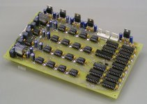
An important project update, the D-I 16 core is up and running.
I added a photograph of the new D-I 16 core PCB, it's a complete D-I DAC with timing-chain, UHS buffers, 4 X 4 DAC matrix, balanced I/V converters, diff amp's, output attenuator and power supply regulators. All that's necessary to get it up and running is a small power supply (+20V, -20V, +10V), and a I2S signal.
Today I manufactured the D-I 16 core PCB and assembled it, during testing it appeared to be a zero defect design. Everything worked flawlessly the first time I switchted it on. The PCB dimensions are 11.6 X 18.9 X 2.5 cm. As for the D-I 16 core sound quality, during a 1 hour listening test, it baffled me, now it's very difficult to hear a difference with the octal D-I DAC core using the TDA1541A. I guess it's the extensive decoupling, short traces and UHS buffers that made the D-I 16 catch-up with the octal D-I DAC, and there is the higher resolution enhancement of course.
This D-I DAC is not difficult to build, just a single PCB and only 3 SMD components. It took me about one hour to assemble, and I even had to solder all components on both sides and add 84 via's. The professional PCB's only need to be soldered on one side and is much easier to assemble. The small dimensions also make it ideal for upgrading a CD player.
The D-I 16 core is a cool runner, even the 2 voltage regulators that drive the DAC matrix will run without heatsink. The DAC chips stay cool as well, it only takes about 7 watts! OP-amps included. It ran for over an hour without any cooling.
Hi all,
An important project update, the D-I 16 core is up and running.
I added a photograph of the new D-I 16 core PCB, it's a complete D-I DAC with timing-chain, UHS buffers, 4 X 4 DAC matrix, balanced I/V converters, diff amp's, output attenuator and power supply regulators. All that's necessary to get it up and running is a small power supply (+20V, -20V, +10V), and a I2S signal.
Today I manufactured the D-I 16 core PCB and assembled it, during testing it appeared to be a zero defect design. Everything worked flawlessly the first time I switchted it on. The PCB dimensions are 11.6 X 18.9 X 2.5 cm. As for the D-I 16 core sound quality, during a 1 hour listening test, it baffled me, now it's very difficult to hear a difference with the octal D-I DAC core using the TDA1541A. I guess it's the extensive decoupling, short traces and UHS buffers that made the D-I 16 catch-up with the octal D-I DAC, and there is the higher resolution enhancement of course.
This D-I DAC is not difficult to build, just a single PCB and only 3 SMD components. It took me about one hour to assemble, and I even had to solder all components on both sides and add 84 via's. The professional PCB's only need to be soldered on one side and is much easier to assemble. The small dimensions also make it ideal for upgrading a CD player.
The D-I 16 core is a cool runner, even the 2 voltage regulators that drive the DAC matrix will run without heatsink. The DAC chips stay cool as well, it only takes about 7 watts! OP-amps included. It ran for over an hour without any cooling.
Attachments
DEM sync clock diagram
Hi Gopher,
Thanks for your reply [post #1103]
You need the schematic diagram of post #353, it's the same as used in the octal D-I DAC. It basically divides BCK by 16. BCK needs to be 44.1 KHz, if it's higher, you need to add a divider. Anyway the output frequency must be 176.4 KHz. Injecting a DEM clock might add noise to the DAC chip's, therefore I used a attenuator, two filters and a simple ringcore transformer to maintain isolation between both analog and digital ground. If you just want to do a quick test first, you can connect all 470pF capacitors directly to R2 (47R)
When disconnecting both pin 16 and 17, the TDA1541A DAC chip may work just as well for some time, but sooner or later distortion starts to appear (clearly audible with low level signals).
Cheers,
John
Dear John,
Yummy!
I added a photograph of the new D-I 16 core PCB, it's a complete D-I DAC with timing-chain, UHS buffers, 4 X 4 DAC matrix, balanced I/V converters, diff amp's, output attenuator and power supply regulators. All that's necessary to get it up and running is a small power supply (+20V, -20V, +10V), and a I2S signal.
Yummy!
Hi ecdesigns.
I have spent the last few hours reading the thread. I must say I like the idea of doing the NOS DAC. I myself design DAC's (the oversampled noise shaped ones..blah blah blah.....) Anyways, I have an idea you might want to try (i dunno if you will) but I put it out there. When you sum up the 16 currents from the 16 DAC's why not weight the currents? What I mean is use a different reistor in the I/V converter. The weighting you use can be determined the same way one would calulate the coefficients for an FIR filter. That way you can make a low pass (linear phase) filter with the 16DAC's Of course, the more the better, if you had a 32DAC version, then you could essentially have a 32 TAP FIR filter made in the analog domain.
Just a thought, let me know if you interested. I could even tell you the resistor values if you like.
By the way, when you add analog signals that have uncorrelated noise, which is what you are doing, the noise adds RSS (sqrt(n1^2+n2^2)) and the signal adds normally. So you basically get an extra ~3dB of SNR for using 2DACS. This does make the assumption the noise is uncorrelated and the noise floor is limited by the DAC and not the input digital data which is only 16bit.
In the 16DAC case, you will of increased your theoretical SNR by 30dB. Of course this is not likely since you have now made the noise of your DAC so low your now limited by the digital data noise floor, about -96dB for 16 bits.
CLD
dusfor99 said:I have an idea you might want to try (i dunno if you will) but I put it out there. When you sum up the 16 currents from the 16 DAC's why not weight the currents? What I mean is use a different reistor in the I/V converter. The weighting you use can be determined the same way one would calulate the coefficients for an FIR filter. That way you can make a low pass (linear phase) filter with the 16DAC's Of course, the more the better, if you had a 32DAC version, then you could essentially have a 32 TAP FIR filter made in the analog domain.
Just a thought, let me know if you interested. I could even tell you the resistor values if you like.
Creative thought
One question: You cannot just put those outputs in parallel again, so I assume your idea is to feed those 16 (or 32) signals in a summing amplifier again ?
have you a circuit study of your idea ?
best
doede
www.dddac.de
Bck
Bck in I2S = 2.8224 Mhz (11.2896 / 4 )
And 2.8221 / 16 gives needed 176.4 kHz
Added some dividers straight away after the separate clock. All reclocked signals can be distributed to dac then.
it's the same as used in the octal D-I DAC. It basically divides BCK by 16. BCK needs to be 44.1 KHz
Bck in I2S = 2.8224 Mhz (11.2896 / 4 )
Anyway the output frequency must be 176.4 KHz
And 2.8221 / 16 gives needed 176.4 kHz
Added some dividers straight away after the separate clock. All reclocked signals can be distributed to dac then.
In the 16DAC case, you will of increased your theoretical SNR by 30dB. Of course this is not likely since you have now made the noise of your DAC so low your now limited by the digital data noise floor, about -96dB for 16 bits.
Sorry inthe 16DAC case, it will increase your SNR by about 15dB not 30dB. My mistake.
CLD
progress report?
Hi EC et all,
Sorry for not posted any pictures of my SMD logic tower of EC's timing chain http://www.diyaudio.com/forums/showthread.php?postid=915913. My wife is out of town with the camera until Tuesday.
I have lots of experience with NOS TDA1543 DAC with a single chip. I have 7 that I tweak, different power transformers, by-pass caps, break-in time are the tweaks/changes I make as try to come up with the best implementation.
Lately I went back to the start of this thread and it all made sense and so I ordered parts and started modifying my second favorite DAC. Keeping my favorite as a reference.
I built the timing chain using SMD parts into a tower which is the same height as a tower of 8 TDA1543. I only had enough TDA1543 chips on hand for a quad version, more chips should arrive next week.
I had to order parts for tower but in the mean while I paralleled the 4 TDA1543 chips, changed the IV resistors and soon noticed an nice increase in resolution over a single TDA1543 (odd that it took me so long to try the paralleling TDA1543) And within days this parallel DAC (which prior to being parallel was not my favorite because of smaller power transformers) became my favorite DAC.
Parts from digikey.ca arrive to build the logic tower and a week goes by while I build it:
8 296-15733-1-ND IC HEX BUFF/LINE DRVR 3ST 16SOIC
25 296-9259-5-ND IC 8-BIT SHIFT REGISTER 16-SOP
10 493-2333-1-ND CAP TANTALUM 4.7UF 10V 20% SMD
20 493-2336-1-ND CAP TANTALUM 0.1UF 35V 20% SMD
5 LM2940T-8.0-ND IC REGULATOR LDO 1A 8.0V TO-220
5 3318F-202-ND TRIMPOT 2K OHM 6MM CARBON
5 549XBK-ND RES 549 OHM 1/4W 1% METAL FILM
5 348XBK-ND RES 348 OHM 1/4W 1% METAL FILM
5 174XBK-ND RES 174 OHM 1/4W 1% METAL FILM
5 681XBK-ND RES 681 OHM 1/4W 1% METAL FILM
5 374XBK-ND RES 374 OHM 1/4W 1% METAL FILM
5 340XBK-ND RES 340 OHM 1/4W 1% METAL FILM
5 187XBK-ND RES 187 OHM 1/4W 1% METAL FILM
5 274XBK-ND RES 274 OHM 1/4W 1% METAL FILM
3 LM2937ET-8.0-ND IC REGULATOR LDO TO-220
8 296-9268-5-ND IC HEX BUFF/LINE DRIVER 16-SOIC
I place the logic tower which includes buffers/drivers beside the quad TDA1543 tower. Cut WS and Data pins on the DAC tower, buffer/drive the Clock line to the TDA tower and Data and WS part of the logic tower. Attach the logic tower to the DAC tower using the appropriate DATA and WS taps from the logic tower. Power it up and it works. It sounds good. Pull out the old 10MHz scope and look at some 1KHz and up test signals and they look lovely, like no singe NOS TDA1543 ever could.
Over the next 24 hours of listening and A/B between this quad DI DAC and my previous favorite single TDA1543 DAC it becomes clear that the parallel DAC sounded better then the DI DAC. The single TDA1543 becomes the preferred DAC to listen to once again.
The DI DAC sounds jittery or time smeared (same thing no?).
I pulled out the old scope and looked at DATA and WS pins on the DAC chips and also compared to the single chip DAC. To me it all looks fine but is also the first time I have ever looked at WS or DATA signals before. There were differences, for example any signal that was buffered by the tower had higher amplitude then non buffered, for example the bottom DAC chip in the tower was still directly connected to the I2S lines, except the Clock pin.
Tonight I removed the logic tower except buffering the Clock signal and the quad parallel DAC is once again the winner over my single TDA1543 DAC.
Maybe there is a problem with my implementation of the timing chain. With no picture, I know it is hard to tell. I kept the wires short. They are only 2 CM long between the DAC tower and the logic tower. All unused logic pins are soldered to ground. The WS and DATA taps that are waiting to complete the octal DAC are not connected but sticking out in the free air. 2 CM long.
Could it be like Bernard suggests that a DI DAC is more susceptible to jitter then a single TDA1543. To me it makes sense since a single clock cycle is being subdivided into smaller segments and so it would requires a more accurate clock then a non DI DAC to work properly. EC I often wondered why you were going on so much about reclocking the USB I2S signal. To me and my non DI DACs there is no jitter problem that I can hear.
EC would you mind sharing/posting your reclocking circuit so that I may build and try it as well?
Any thoughts/questions anyone?
Anyone with some TDA1543 to sell please message me
Cheers,
Brent
Hi Brent Welke,
Thanks for your reply [post#1119],
Seems something isn't working correctly as the D-I DAC's I build don't have this problem at all, besides I had two diyAudio members come over and listen to both the TDA1541A and the TDA1543 D-I DAC's, sure they must have noticed something if the output signal was showing the problems you described. But I have to admit I use at least 8 DAC chip's in D-I mode. You could also check the following:
DAC1 receives BCK, WS and DATA
DAC2 receives BCK(inverted)!, WS32, DATA32
DAC3 receives BCK(inverted)!, WS16, DATA16
DAC4 receives BCK(inverted)!, WS48, DATA48
The BCK clock signal for both the timing-chain and the DAC chips must be buffered to keep jitter low. Use the following buffer scheme:
BCK > buffer > timing-chain (not jitter sensitive)
BCK > buffer > DAC1 (jitter sensitive)
BCK > inverting buffer > DAC2,3,4...n (jitter sensitive)
So use buffered BCK signals exclusively.
The 4 parallelled TDA1543's using passive I/V may exeed 25mV AC compliance by far, causing significant distortion, the 25mV AC compliance will always be a big problem using passive I/V's. Don't forget the output current is 4 times higher than your single TDA1543 DAC. You could run a simple test, just parallell the 4 DAC's and supply BCK, DATA and WS to them all (no timing-chain), if the sound doesn't improve, the problem is in the passive output stage.
As for jitter sensitivity, the D-I DAC's are comparable to NOS DAC's as no oversampling is used. I payed so much attention to jitter because as the sound quality keeps improving, the digital sound source (jitter) will become a limiting factor. Sure, like with all DAC's, lower jitter improves sound quality.
If you like I can post part of the D-I 16 output stage.
Cheers,
John
- Home
- Source & Line
- Digital Line Level
- Building the ultimate NOS DAC using TDA1541A