New octal D-I DAC core completed
Hi tubee,
Thanks for your reply [post #1060]
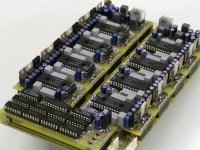
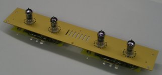
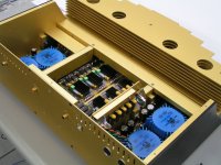
Would this octal D-I DAC core fit your CDP? have a look at the attached picture. Yes, the new octal D-I DAC core is ready, it measures 21.9 X 13.4 X 3.5 cm.
The DEM sync clock and UHS buffers are now integrated in the new timing-chain module, greatly simplifying the analog mainboard.
The new timing-chain module only accepts Philips format, but a small external converter can be used if the Sony format is to be used. The WS delay circuit is completely modified to reduce the amount of chip's needed. The rest of the logic is contained in a PALCE16V8 (programmable logic device). I need to create some more space between the shift-register chip's, and perhaps provide a jumper for inverting data. With this jumper a selection can be made between balanced or single-ended DAC operation.
All this octal D-I DAC core needs to function is a power supply and a Philips format I2S source. If only the OP-amp outputs are used, output impedance is approx. 55 Ohms.
I found some ECA high-quality audio grade electrolytic capacitors from Panasonic, they have a special electrolyte and a modified outer sleeve, so I used them in the new octal D-I DAC core for testing.
Hi tubee,
Thanks for your reply [post #1060]
Would this octal D-I DAC core fit your CDP? have a look at the attached picture. Yes, the new octal D-I DAC core is ready, it measures 21.9 X 13.4 X 3.5 cm.
The DEM sync clock and UHS buffers are now integrated in the new timing-chain module, greatly simplifying the analog mainboard.
The new timing-chain module only accepts Philips format, but a small external converter can be used if the Sony format is to be used. The WS delay circuit is completely modified to reduce the amount of chip's needed. The rest of the logic is contained in a PALCE16V8 (programmable logic device). I need to create some more space between the shift-register chip's, and perhaps provide a jumper for inverting data. With this jumper a selection can be made between balanced or single-ended DAC operation.
All this octal D-I DAC core needs to function is a power supply and a Philips format I2S source. If only the OP-amp outputs are used, output impedance is approx. 55 Ohms.
I found some ECA high-quality audio grade electrolytic capacitors from Panasonic, they have a special electrolyte and a modified outer sleeve, so I used them in the new octal D-I DAC core for testing.
Attachments
Hi MiiB,
Thanks for the compliments [post #1051]
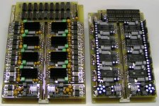
I already experimented with jfet outputs, perhaps I could design a small jfet I/V diff amp module later. After a lot of experimenting and listening tests, I still prefer the tuned OPA627 I/V because it produces the most realistic sound so far.
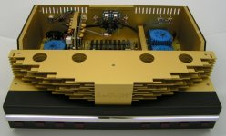
The tube output of the octal D-I DAC consists of a differential tube amplifier (ECC83) and a double cathode follower (ECC81). Very high output voltages are used, the maximum output voltage of the tube stage is about 30Vpp, it enters a programmable attenuator to obtain semiconductor, tube or mixed mode. Due to this setup, the tube output stage has no problem with different loads. As noted earlier on this thread, the combination of both tube and OPA627 output creates a wonderful natural sound, it can't be obtained by semiconductor or tube amplifier only.
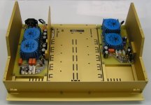
I added a photograph of both analog mainboards for comparison.
Cheers John
Thanks for the compliments [post #1051]
I already experimented with jfet outputs, perhaps I could design a small jfet I/V diff amp module later. After a lot of experimenting and listening tests, I still prefer the tuned OPA627 I/V because it produces the most realistic sound so far.
The tube output of the octal D-I DAC consists of a differential tube amplifier (ECC83) and a double cathode follower (ECC81). Very high output voltages are used, the maximum output voltage of the tube stage is about 30Vpp, it enters a programmable attenuator to obtain semiconductor, tube or mixed mode. Due to this setup, the tube output stage has no problem with different loads. As noted earlier on this thread, the combination of both tube and OPA627 output creates a wonderful natural sound, it can't be obtained by semiconductor or tube amplifier only.
I added a photograph of both analog mainboards for comparison.
Cheers John
Attachments
Thanks for reply. Suggesting the the Jfet approach was the have some of the undisputed qualities of the tubes in a more compact and less size demanding package. I see you have turned to the more obtainable 1543 dacs which is good (That is if you plan to sell any).
My only problem with the Jfets is the output stage wherer you really want some current. hence the Pjfet used in pass zen variation 8. was suggested. Why do you operate with differntial signals. wouldn't singleended be enough. Is the signal from the TDA balanced or is it singleended with a 0. at a specific voltage.
Best regards
Michael Børresen
Hi MiiB,
Thanks for your reply [post #1063]
Tubes produce a very specific sound (harmonic spectrum), it's very difficult to mimmic this with jfet's. The warmth and transparency of tube amplifiers is unique.
The TDA1543 was intended for a compact 16 X D-I USB DAC, but I already have other plans with it as well. If the TDA1541A availability becomes really problematic, I plan to put a 64 X TDA1543 D-I core in the "octal D-I DAC". Rated power consumption will be around 18 Watts, so that shouldn't be a problem.
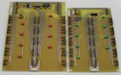
I use a differential setup because it enables DC-coupled operation, avoiding capacitors or transformers in the signal path, this ensures lowest possible phase distortion. I also noticed, interference and distortion are lower due to suppression of common noise.
DAC group 1 (not inverted) enters a tuned OP-amp I/V converter and provides the inverted output voltage containing a DC offset (I/V converter reverses polarity).
DAC group 2 has it's data lines inverted (this is handled by the timing-chain logic) it also enters a tuned OP-amp I/V converter and provides the non-inverted output voltage, also with a DC offset.
Now both signals (inverted and non-inverted) enter a diff amp, both DC offset voltages and common noise are cancelled out, but since one DAC output was inverted, the AC output voltage is doubled. So now we have a single ended output voltage with almost 0V DC component, and twice the amplitude.
The outputs of the OP-amp I/V converters are also fed to a differential input tube amplifier stage, with a single ended output. The output's of both amplifier stages (that run simultaneously) enter a programmable attenuator. The signal levels in the octal D-I DAC are way higher when compared to other DAC's. The OP-amp stage outputs approx. 20vpp, the tube stage outputs approx. 30vpp, so for the mixed mode a 50vpp signal is available. This is done to boost even the smallest details, and keeping both noise and interference levels very low.
I added a picture of both analog mainboards without the modules placed.
Best regards,
John Brown
Thanks for your reply [post #1063]
Tubes produce a very specific sound (harmonic spectrum), it's very difficult to mimmic this with jfet's. The warmth and transparency of tube amplifiers is unique.
The TDA1543 was intended for a compact 16 X D-I USB DAC, but I already have other plans with it as well. If the TDA1541A availability becomes really problematic, I plan to put a 64 X TDA1543 D-I core in the "octal D-I DAC". Rated power consumption will be around 18 Watts, so that shouldn't be a problem.
I use a differential setup because it enables DC-coupled operation, avoiding capacitors or transformers in the signal path, this ensures lowest possible phase distortion. I also noticed, interference and distortion are lower due to suppression of common noise.
DAC group 1 (not inverted) enters a tuned OP-amp I/V converter and provides the inverted output voltage containing a DC offset (I/V converter reverses polarity).
DAC group 2 has it's data lines inverted (this is handled by the timing-chain logic) it also enters a tuned OP-amp I/V converter and provides the non-inverted output voltage, also with a DC offset.
Now both signals (inverted and non-inverted) enter a diff amp, both DC offset voltages and common noise are cancelled out, but since one DAC output was inverted, the AC output voltage is doubled. So now we have a single ended output voltage with almost 0V DC component, and twice the amplitude.
The outputs of the OP-amp I/V converters are also fed to a differential input tube amplifier stage, with a single ended output. The output's of both amplifier stages (that run simultaneously) enter a programmable attenuator. The signal levels in the octal D-I DAC are way higher when compared to other DAC's. The OP-amp stage outputs approx. 20vpp, the tube stage outputs approx. 30vpp, so for the mixed mode a 50vpp signal is available. This is done to boost even the smallest details, and keeping both noise and interference levels very low.
I added a picture of both analog mainboards without the modules placed.
Best regards,
John Brown
Attachments
Dear ECdesign,
I have been reading this post for about the last 2 hours, started at page one and stopped at page 40 or so. Thought it would be better to go directly to the end.
I am very impressed to read about the enthousiastic post of so many reader and the expertise of most of them. I started about 25yrs ago prepping some simple ams, but this, this is major league !!
I bought A CDPRO2M player with I2S output, and would very much like to build the proposed DAC.
Is there a kit available (since i skipped abt 60 pages...) ? Or are PCB's the current status ?
I found also another interesting DAC in Romania at www.audiokit.ro which uses I2S but this is I think old school thinking.
Hi John.
Again very good work with new D-I core design. Tonight i will measure if it can be placed in CDP. It has a reasonably quick working modified CDM-2 in it. CDM 4 is faster though, have a cdp with 1543 dac. How big is the PS for the DI dac including transformer?
Nice caps, i just bought 4 Black Gate Nx caps to try in 304mk2 for opamp decoupling. For digital decoupling purposes Sanyo Oscon (Conrad) should work fine too.
John, your new design D-I core will fit into the CDP enclosure i fabricated. With some fiddling a tube stage also, but then only one tube i presume. The PS + transformer for the D-I dac could be placed behind original transformer, there is place for a 40W ringcore.
The best solution is still a separate dac. Managed to lower background noises in the 304, can remotely hear the searching noise of servo between tracks with headphones!
The best solution is still a separate dac. Managed to lower background noises in the 304, can remotely hear the searching noise of servo between tracks with headphones!
John,
Your new boards are works of art. I wish you can build a housing that will show them off - perhaps an acrylic top cover that will show selected internal parts (ie, octal set of chips and tube output section). This with polished aluminum housing with selected anodized black/blue accents would be so nice - like the MBL 1511E DAC:
http://www.mbl-germany.de/english/start.html
A more modest housing like this compared to your original over the top design would suit most people I think.
Keep up the awesome work!
New octal D-I DAC housing
Hi MGH,
Thanks for the compliment [post #1069]
The new boards also sound very impressive, even without tube output stage. Sound is crystal clear and rich of detail, I even noticed some things on familiar CD's I haven't heared yet.
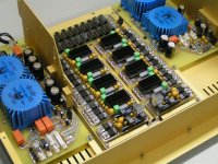
This is the most basic setup, the octal D-I DAC core and a small 20 watts power supply.
By the way, I completed the timing-chain modifications, I created some more space between the shiftregisters and added a new feature. A jumper selectable data inverter, so if you don't like to use balanced DAC outputs, placing a jumper is all it takes to disable inverting of data lines D32, D40, D48 and D56.
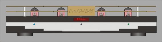
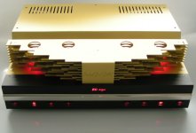
As for the housing, there will be a nice solution. I added a rough sketch of it. The housing will be made of annodized aluminum and a stainless steel front panel. I plan to mount all PCB's on the bottom plate, including the tube output modules. The tubes are now placed on the component side and are partially located inside the DAC housing. The new housing will be very flat, approx. 5 cm high. If desired, the top cover can be made of Lexan (polycarbonate) a clear unbreakable plastic. Now the whole interior of the octal D-I DAC is visible. I will use two multicolour (RGB) LED's for both input selection and output mode indicators. The round spot in the center is the remote control receiver.
Hi MGH,
Thanks for the compliment [post #1069]
The new boards also sound very impressive, even without tube output stage. Sound is crystal clear and rich of detail, I even noticed some things on familiar CD's I haven't heared yet.
This is the most basic setup, the octal D-I DAC core and a small 20 watts power supply.
By the way, I completed the timing-chain modifications, I created some more space between the shiftregisters and added a new feature. A jumper selectable data inverter, so if you don't like to use balanced DAC outputs, placing a jumper is all it takes to disable inverting of data lines D32, D40, D48 and D56.
As for the housing, there will be a nice solution. I added a rough sketch of it. The housing will be made of annodized aluminum and a stainless steel front panel. I plan to mount all PCB's on the bottom plate, including the tube output modules. The tubes are now placed on the component side and are partially located inside the DAC housing. The new housing will be very flat, approx. 5 cm high. If desired, the top cover can be made of Lexan (polycarbonate) a clear unbreakable plastic. Now the whole interior of the octal D-I DAC is visible. I will use two multicolour (RGB) LED's for both input selection and output mode indicators. The round spot in the center is the remote control receiver.
Attachments
Ems-rfi
Dear EC,
You know that I am very interested in your 8 dac.
I still have to make an appointment to come to listen at your place.
But now I have a question.
Did you test the octal DAC in a place full off EMS
like the center of Rotterdam ??
My mod CD104 (2 tda1541) sounded crystal clear after 01.00 hours until about 06.00 and horrible during the rest of the day
until I did EMS hunting using Quido Tent's exellent article (1999 !)
on his Website.
I found out that the EMS disturbing the CD 104 did not come from the (internal) powersupply but the groundloops picked it up.
So what about the 8 dac and a EMS attack ??
Thanks in advance for answering.
Best regards,
Onno
Octal D-I DAC EM immunity
Hi Onnosr,
Thanks for your reply [post #1071]
About the octal D-I DAC electromagnetic immunity, just have a look at the photographs and schematic diagrams I posted. You will find the following:
- Double mains filter is used
- Encapsulated ringcore transformers are used to minimize emitted electromagnetic field
- CLC filters are used for each voltage regulator
- Ceramic decoupling cap's are placed directly across the power supply pins of all chip's
- Every module has it's own voltage regulator(s) on board
- Pre-regulators are used
- Separate analog and digital ground
- A star grounding scheme is used
- Isolation transformer for the DEM synchronization clock
- The entire analog mainboard is covered by a grounded screening plate
- The analog mainboard has a large ground plane with a special pattern
- The internal signal levels used in the octal D-I DAC are very high, so they are less sensitive to EM interference
- The resistive output attenuator ensures rock-solid operation, regardless of the connected load
- The octal D-I DAC uses no oversampling, so it's much less sensitive to interference
- The HF signals eminating from the DAC chip current outputs are already attenuated by design (D-I mode)
- The aluminum DAC housing acts as a screen
- The tubes are screened by a protective grille
- The differential I2S inputs causes less interference and avoids ground loop problems
- PCB's have been routed manually for optimal performance.
- The octal D-I DAC has no critical (master) clock circuits that are sensitive to interference
- The tuned OP-amp I/V has a very stable tuned negative feedback loop
- The USB interface has special trace patterns for optimal distribution of the clock signals
- All I2S signals are buffered, BCK is buffered by separate tiny-logic UHS buffers, avoiding inter-chip crosstalk and interference
- Differential I2S transmitters and receivers use a separate chip (DS8921) for BCK, avoiding cosstalk / jitter
In short, the octal D-I DAC is very immune to EM fields as I have taken the necessary precautions during design to avoid interference. Basically keeping interference levels low is a must in High-End equipment, just read this thread and you will find that I paid a lot of attention reducing interference.
The octal D-I DAC should work flawlessly in a EM polluted environment.
By the way, I just received a phonecall, the octal D-I DAC aluminum parts have been annodized
Best regards,
John
Re: Octal D-I DAC EM immunity
The octal D-I DAC should work flawlessly in a EM polluted environment.
Dear John,
Thanks for your long well documented reply.
I know already that you are not stupid")
and oc have taken all the care against EMC.
But my place, near CS Rotterdam and 100 m
away from a GSM tower and 1000 meters away from a couple of FM (UHF) broadcast transmiters ( I can see the antennas), is a really bad EM place.
As a radioham (PA0ONO) it is FI no fun to listen - everywhere the noise level has a signal of S8 to 10 decibel over S9.
On a scope everywhere spikes.
For audio I use for recording a Fireface 800 from RME. - those RME boys have done everything against EM, they told me .
But still I have to put on every cable a ferrit clamp.
So I did to all my other equipment. Ferrrit coils in the speakerwires, etc. etc. and still it is audible !
If you like it you are invited to test the dac at my place.
(food and drinks are included)
I suppose that you know the document from Tim Williams "EMC for
product designers " (2001 third edition) If not I will email it to you (3.6 mb)
Last point: do you have already a roughly indication about the cost for the simplified dac (usb and no tube I/V stage).
Best Regards
Onno
The octal D-I DAC should work flawlessly in a EM polluted environment.
Dear John,
Thanks for your long well documented reply.
I know already that you are not stupid
and oc have taken all the care against EMC.
But my place, near CS Rotterdam and 100 m
away from a GSM tower and 1000 meters away from a couple of FM (UHF) broadcast transmiters ( I can see the antennas), is a really bad EM place.
As a radioham (PA0ONO) it is FI no fun to listen - everywhere the noise level has a signal of S8 to 10 decibel over S9.
On a scope everywhere spikes.
For audio I use for recording a Fireface 800 from RME. - those RME boys have done everything against EM, they told me .
But still I have to put on every cable a ferrit clamp.
So I did to all my other equipment. Ferrrit coils in the speakerwires, etc. etc. and still it is audible !
If you like it you are invited to test the dac at my place.
(food and drinks are included)
I suppose that you know the document from Tim Williams "EMC for
product designers " (2001 third edition) If not I will email it to you (3.6 mb)
Last point: do you have already a roughly indication about the cost for the simplified dac (usb and no tube I/V stage).
Best Regards
Onno
DAC annodized aluminum parts have arrived
Hi all,
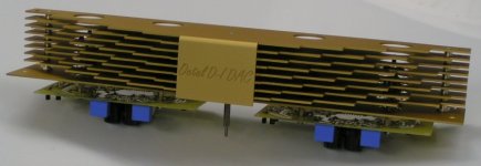
The octal D-I DAC annodized aluminum parts have arrived, as you may have guessed I couldn't wait and soon started to assemble some parts, after all I had to live without the octal D-I DAC sound for quite a while. I added a picture of the tube chassis part.
Hi all,
The octal D-I DAC annodized aluminum parts have arrived, as you may have guessed I couldn't wait and soon started to assemble some parts, after all I had to live without the octal D-I DAC sound for quite a while. I added a picture of the tube chassis part.
Attachments
- Home
- Source & Line
- Digital Line Level
- Building the ultimate NOS DAC using TDA1541A