Hi Alexandre,
Linear power supply noise is neglible compared to SMPS when the linear power supply is designed correctly.
SMPS also contains diode rectifiers, both for mains voltage rectifier and output voltage rectifier. So double trouble here")
This would still require expensive high order filters, perfect screening of the enire SMPS and a suitable safety earth connection for bleeding RF noise. It also requires lowest possible stray capacitance between switch-mode transformer primary and secondary windings as switching frequencies are between 60KHz and 500KHz typical.
Power factor - Wikipedia, the free encyclopedia
A well designed SMPS will have the advantage of high efficiency, smaller size and lower weight compared to linear power supplies.
It is very likely that they are a lot worse in terms of EMI and noise compared to linear power supplies.
This outlines the practical problems that are encountered with SMPS that are so difficult to solve. Think of stray capacitance in components, EMI, and ground loops.
I was thinking, aren´t diode rectifiers just as bad as SMPS, with their switching? They certainly are generating EMI on both the mains and the subsequent circuit.
Linear power supply noise is neglible compared to SMPS when the linear power supply is designed correctly.
SMPS also contains diode rectifiers, both for mains voltage rectifier and output voltage rectifier. So double trouble here
SMPS can operate at a chosen optimal frequency that can be very well filtered.
This would still require expensive high order filters, perfect screening of the enire SMPS and a suitable safety earth connection for bleeding RF noise. It also requires lowest possible stray capacitance between switch-mode transformer primary and secondary windings as switching frequencies are between 60KHz and 500KHz typical.
Active PFC (power factor correction) can make the mains current close to senoidal.
Power factor - Wikipedia, the free encyclopedia
So, I think a well designed smps can be better than diode rectifiers.
A well designed SMPS will have the advantage of high efficiency, smaller size and lower weight compared to linear power supplies.
It is very likely that they are a lot worse in terms of EMI and noise compared to linear power supplies.
Of course, the audio currents needs to be decoupled and separated from the pulse currents of the supply. Shunt regulators come to mind.
This outlines the practical problems that are encountered with SMPS that are so difficult to solve. Think of stray capacitance in components, EMI, and ground loops.
Hi Skorpio,
The I/V stage built around the 2SK170 is outdated, one of the problems is that it exceeds TDA1541A output compliance.
The adjustable DC reference voltage takes care of this. It consists of a 1K trimmer with a 1000uF cap between wiper and GND, and another 1000uF cap between the wiper and +5V.
The voltage at the wiper serves as GND connection for the RCA sockets. This works as long as this reference voltage is not short-circuited by other connected equipment.
The trimmer is set for lowest possible DC voltage reading between the wiper of the trimmer and both RCA outputs.
This design requires no coupling caps, it ensures highly transparent playback with optimal bass response and ease of mind that one exceeds the performance of the best film caps available.
Not with the 5V supply. When the supply voltage (for the I/V stage only!) is increased, to say to 10V, it is possible to double the output amplitude by using a 1K I/V resistor. Disadvantage is that the selected bit currents no longer flow back into the 5V supply like the unselected bit currents do. This leads to higher ripple voltage on the 5V supply and increased on-chip jitter levels.
Hi
Thank you for quick answer, but I guess I will have to read the huge tread to get what you talk about

As I understand it not, the schematic I found is outdated....but I would shure like to try it out...
Not with the 5V supply. When the supply voltage (for the I/V stage only!) is increased, to say to 10V, it is possible to double the output amplitude by using a 1K I/V resistor. Disadvantage is that the selected bit currents no longer flow back into the 5V supply like the unselected bit currents do. This leads to higher ripple voltage on the 5V supply and increased on-chip jitter levels.
If you use a +5 volt regulator with return (the -) connected to the +5V TDA1541 supply, I would guess you have returned the bit current flow the correct way? And at the same time raised the i/v voltage to 10V. You could go even higher in voltage.
I have (as mentioned earlier)
tried this concept and it works fine.Koldby
Hi everybody,
I have build my own DAC based on the following schematics:
http://lampizator.eu/lampizator/REFERENCES/Arcam Delta DAC/arcam 70_2 dac section.jpg
According to the schematics, There are 4 tantals capacitors to be mount on 4 legs of TDA 1541, 2 tantals have plus side to earth and the two last one have minus side to earth. Is it right?
Please help me on this master.
Thanks a lot.
BR,
Khanh
Hi 4rgroup,
I assume you are referring to the 0.47uF tantalum caps on pins 7, 8, 18, and 19.
The schematic is wrong. All these 0.47uF tantalum caps should have + connected to GND and - connected to the TDA1541A (voltage on pins 7, 8, 18, and 19 is negative).
According to the schematics, There are 4 tantals capacitors to be mount on 4 legs of TDA 1541, 2 tantals have plus side to earth and the two last one have minus side to earth. Is it right?
I assume you are referring to the 0.47uF tantalum caps on pins 7, 8, 18, and 19.
The schematic is wrong. All these 0.47uF tantalum caps should have + connected to GND and - connected to the TDA1541A (voltage on pins 7, 8, 18, and 19 is negative).
I don't know if this will be useful, or misleading, so I'll add that I'm still using a layout from an old cd player and track lengths (thru hole components) are about the same as the current Red Baron brds - it's a bit prehistoric in comparison to the newer smd designs.
I used the Siemens B32529 1uF on all pins, as the decoupling caps, then added another one for 2uF and noticed an improvement, particularly in the bass - I changed these second additional ones to those Cornell 1uF SMD ones and there appeared to be a small change in the mids/tops but nothing outstanding.
However, I played around with the MSB pin (13,18) quite a lot and ended up there with a 4uF Solen FC cap (of all things!)- not 3.9 or 4.2, but a spot on 4.0uF!
I've tried different DEM reclocking freqs/methods and had some quite different changes in the balance of the sound but I've kept coming back to this weird 4uF setup -
it's all wrong in that the cap leads are ridiculously long, the track lengths are also quite long, and so on, but for the type of ol' fella dac layout that I'm still using, this idea is worth a visit if you have some caps like this -
I tried a number of expensive caps (the Mundorfs, Sidereals, etc) here and the cheap Solen's did the job - I tried a really old couple called WondeCaps and they produced a similar result - no doubt, there are other caps than the ones I tried (about 40, I think) -
For example, the little Mundorf audiophiler 4.0uF white caps gave bloated fat bass and their bigger brother ones were about the same - the Silver version didn't work particularly well at all, and this is how it went. Styrenes also didn't give good results for me.
A small RC network on pins 12 and 19 (1.47nF + 100R) seemed to add an extra clarity to the cymbols but on no other pins (no idea why) but on the Cen output stage, the treble and transients were better without it.
Perhaps this might be useful, or at least, a bit of a laugh - I had a bit of fun with this!
I don't know if this still applies with the more compact versions but it wouldn't be hard to double up on the SMDs - I couldn't get a 'good sound' using 4u of the Siemens or Dubillier smd for pins 13/18
It doesn't make any sort of good engineering, but somehow it seems to work for me ....
I used the Arcam Alpha PCB which has the same design. I can assure you, that removing the caps and replacing these caps with caps soldered directly to the pins was a big step up in sound quality. Actually used 8u smt organic polymer.Hi everybody,
I have build my own DAC based on the following schematics:
http://lampizator.eu/lampizator/REFERENCES/Arcam Delta DAC/arcam 70_2 dac section.jpg
According to the schematics, There are 4 tantals capacitors to be mount on 4 legs of TDA 1541, 2 tantals have plus side to earth and the two last one have minus side to earth. Is it right?
Please help me on this master.
Thanks a lot.
BR,
Khanh
Also put in shunt regs. BG in the power filtering. Lastly, solder BG N caps right on the pins of the power consumers. This board was a good start, but clearly far from state of art.
-15v supply
Back after a long time out and I have been reading a chapter on voltage regulators in Walt Jung's Op Amp applications before I jump in with tda1541a psu in my dac. The tda1541a datasheet has ripple rejections listed of 76 db on +5v , 84 db on -5v and 58 db on -15v. My initial thoughts were the Velleman K8042 symmetric lm317/lm337 looked a good candidate however I am not sure it will cut it on that -15v supply after reading the chapter ( i have not checked the mathematics).
Looking at discrete -15v regulators(lm2990, 7915 variants) lm337 is an improvement in ripple rejection , and i think line and load regulation. I see there is a market in precision regulator replacements (even Naim now does these drop ins). The ones I have seen are surface mount products well beyond my diy skills.
Ok so how what tolerances are needed on the -15v? 16bit reference?
(Appologies if the maths is elsewhere in the thread)
Back after a long time out and I have been reading a chapter on voltage regulators in Walt Jung's Op Amp applications before I jump in with tda1541a psu in my dac. The tda1541a datasheet has ripple rejections listed of 76 db on +5v , 84 db on -5v and 58 db on -15v. My initial thoughts were the Velleman K8042 symmetric lm317/lm337 looked a good candidate however I am not sure it will cut it on that -15v supply after reading the chapter ( i have not checked the mathematics).
Looking at discrete -15v regulators(lm2990, 7915 variants) lm337 is an improvement in ripple rejection , and i think line and load regulation. I see there is a market in precision regulator replacements (even Naim now does these drop ins). The ones I have seen are surface mount products well beyond my diy skills.
Ok so how what tolerances are needed on the -15v? 16bit reference
?(Appologies if the maths is elsewhere in the thread)
JH, don't you want to try without any decoupling capacitors? Another silly idea that works for me
I tried that not long ago, but I found details where lacking, ARTA was showing 0.3% of THD+N, while when after that I tried cornell dubilier 1uF on all decoupling pins THD+N suddenly dropped to 0.03% and the sound was also more detailed than with no decoupling caps.
Most cases where people have experimented with 7915,lm337 or TL431 vs discrete shunts, the shunt comes out on top by a wide margin. I took a first step by replacing lm337 with a Burson Shunt and it was an easy and successful improvement. So if you are not into an expensive diy Salas shunt, the gen 1 Burson Regs are still on 50% clearance for $24 at PartsConnection. I use them and they work well. I am building Salas shunts to replace them in the next gen build but they work well and are a cost effective step up over integrated....
Looking at discrete -15v regulators(lm2990, 7915 variants) lm337 is an improvement in ripple rejection , and i think line and load regulation. I see there is a market in precision regulator replacements (even Naim now does these drop ins). The ones I have seen are surface mount products well beyond my diy skills.
...
Most cases where people have experimented with 7915,lm337 or TL431 vs discrete shunts, the shunt comes out on top by a wide margin. I took a first step by replacing lm337 with a Burson Shunt and it was an easy and successful improvement. So if you are not into an expensive diy Salas shunt, the gen 1 Burson Regs are still on 50% clearance for $24 at PartsConnection. I use them and they work well. I am building Salas shunts to replace them in the next gen build but they work well and are a cost effective step up over integrated.
Thanks. That reads like the path I would have followed. I have not seen a salas shunt regulator.
Hi wlowes,
Shunt regulators offer no significant advantages (performance) over equally well designed series regulators.
The Burson shunt regulator has been discontinued and replaced by the Burson low noise regulator that is a series regulator:
Low Noise Regulator
I assume that the new version should perform better than the previous shunt regulator version.
The new Burson low noise regulator was compared here:
Superpower Super Regulator by Belleson
Based on this, performance isn't that great.
Most cases where people have experimented with 7915,lm337 or TL431 vs discrete shunts, the shunt comes out on top by a wide margin.
Shunt regulators offer no significant advantages (performance) over equally well designed series regulators.
I took a first step by replacing lm337 with a Burson Shunt and it was an easy and successful improvement. So if you are not into an expensive diy Salas shunt, the gen 1 Burson Regs are still on 50% clearance for $24 at PartsConnection
The Burson shunt regulator has been discontinued and replaced by the Burson low noise regulator that is a series regulator:
Low Noise Regulator
I assume that the new version should perform better than the previous shunt regulator version.
The new Burson low noise regulator was compared here:
Superpower Super Regulator by Belleson
Based on this, performance isn't that great.
John, I appreciate your comments in the context of the this thread which is about Ultimate performance.
RE: Shunt regulators offer no significant advantages (performance) over equally well designed series regulators.
Don't disagree. But, ash_dac was asking about the use of (lm2990, 7915 variants) and lm337 as an improvement over their performance. So I point out that the OLD Burson shunt is available at discount prices at Partsconnection due to the fact that it is discontinued. I do not say it is the ultimate solution, but it is a drop in replacement for a 7915 at reasonable price. I can repeat that I have used it and it is a significant improvement in sound over the LM337 it replaced. I agree that well designed series and shunt regs with well chosen parts perfectly laid out will indeed have both improved measurement and improved sound. But this is obtained at considerable investment in time and $$. For someone considering the integrated circuits costing <$1 it's not a bad path into the fray.
I also have used very simple and inexpensive series reg designs with good outcome.
You, Salas, IKO and others have spent years perfecting the art with outstanding outcome.
But for the sake of ash_dac who may be interested in the range of choices available at reasonable investment resulting in lower noise and better sound.
7905 = $0.5
TL431 = $1
TNT Zener emiter follower = about $5 in parts and 1 hour
Discontinued old Burson =$20
Salas Shunt PCB and suggested parts = About $45 and a bit of time
The Burson shunt regulator has been discontinued and replaced by the Burson low noise regulator that is a series regulator:
I have no experience with Burson current products and will not go that direction because at $50 each, I can build a really well designed shunt or series reg and get better results.
Hi wlowes,
Based on the comparison, the plain 78XX regulator performs a lot better than the much more expensive Burson regulator. It may be a drop-in replacement but it is unlikely to lead to a cleaner power supply.
DACs and streamers that suffer from slightest jitter will introduce clearly audible distortion. Jitter is affected by power supply noise and ripple (trigger uncertainty, masterclock that is extremely sensitive to power supply noise and so on).
Degrading to a poorer performing voltage regulator will increase jitter but it will also change the jitter spectrum. The changed jitter spectrum may lead to better perceived sound quality due to the masking effect. This however is moving away instead of towards ultimate transparency.
It is difficult to construct a voltage regulator that does everything right. Every regulator has its advantages and disadvantages.
Every voltage regulator needs a reference voltage, this is the most important part of the regulator. When it varies (with changing input voltage for example), the output voltage varies too as it is derived from this reference voltage. Often LEDs or zener diodes are used. These do not offer a reference voltage that is stable enough, not even when operated at a constant current. Often the CCS feeding the reference voltage LED is also based on a LED as reference. In short, this does not lead to required ultra stable reference voltage. Bandgap reference circuits offer a much more stable output voltage, but also generate more noise compared to a LED. This noise can be filtered out with a RC or LC filter for example. Then we have both, an extremely stable reference voltage and low noise.
Next problem is that the circuit connected to this RC filter will need to have highest possible input impedance. If not, current drawn from the RC or LC filter will still lead to voltage fluctuations. One possible option is using a MOSFET.
In order to provide good load and line regulation we need plenty of gain. In practice an open loop gain of 10 million or more is required. When the feedback loop is closed, oscillations and instabilities may occur, especially when the load current changes suddenly. This is the most difficult part of the voltage regulator, keeping the circuit as stable as possible. It helps to design a circuit that has largest possible bandwidth, then a unity gain circuit is the most logical solution. This means that the reference voltage must be almost equal to the desired output voltage.
Other issue is that a (perfect) voltage regulator will pollute the unregulated input voltage. This can be explained by the varying load current. When multiple voltage regulators share one common input voltage, cross pollution can occur (one voltage regulator pollutes the input voltage of the other and vice versa). Therefore it is desirable to feed each voltage regulator with a separate unregulated voltage.
Since the voltage regulator has to correct for both, varying input voltage and varying load current, both will show up in the error signal and may crosstalk to the output, especially when high frequency ripple voltage is present (digital circuit), this high frequency will then act as carrier for the error signal part from the input voltage. The input voltage noise can still reach the output through "radio transmission".
The mains voltage is highly polluted nowadays, this problem needs to be tackled too. One can use the transformer itself as low pass filter by connecting a 2u2 film cap on the secondary windings. The transformer type also matters a lot, each transformer type has different stray capacitance between primary and secondary windings. This stray capacitance should be kept as low as possible.
This type of transformer has low stray capacitance (25pF typical) because of the way it is constructed:
FL6/9 - BLOCK - TRANSFORMER, 6VA, 2 X 9V | Farnell Nederland
These are not bad either (50pF typical):
PT 7.5/2/9 - BLOCK - TRANSFORMER, 7.5VA, 2 X 9V | Farnell Nederland
These transformers do have a problem, external magnetic field. So it is advised to use these in an external power supply unit and never put these inside the DAC.
This Toroidal transformer (300pF typical) has low external magnetic field and may be placed inside the DAC.
Buy Toroidal Transformers Transformer Toroidal PCB 7VA 2x9V o/p Nuvotem 70031K online from RS for next day delivery.
Using a number of separate (toroidal) transformers to power a DAC is a bad idea because every transformer has certain stray capacitance and all capacitances are summed. Example, 4 toroidal transformers form above link are used to power a DAC, summed stray capacitance equals 1200pF!
Transformer stray capacitance increases with transformer power (VA). When using over-dimensioned transformers, stray capacitance is significantly increased and more mains interference can reach the DAC through this stray capacitance.
So it is best to use a single (custom) transformer with multiple secondary windings that is correctly dimensioned (not overdimensioned) for the connected load.
Logical conclusion is also that shunt regulators are less suitable as these consume almost twice the amount of power of a series regulator. This requires doubling the transformer capacity and thus increasing transformer stray capacitance.
The most elegant solution is a DAC that draws as little power as possible (series regulators) connected to a small external transformer of the type showed in the first link (flat transformers). This will give best possible performance while running on a heavily polluted mains voltage.
Mains voltage pollution is mainly caused by energy saver (LED) lamps that run on unfiltered switch-mode converters (low-cost), and every device that contains a SMPS. It helps to switch-off or unplug these devices before a listening session as these always degrade sound quality to some extent.
but it is a drop in replacement for a 7915 at reasonable price
Based on the comparison, the plain 78XX regulator performs a lot better than the much more expensive Burson regulator. It may be a drop-in replacement but it is unlikely to lead to a cleaner power supply.
DACs and streamers that suffer from slightest jitter will introduce clearly audible distortion. Jitter is affected by power supply noise and ripple (trigger uncertainty, masterclock that is extremely sensitive to power supply noise and so on).
Degrading to a poorer performing voltage regulator will increase jitter but it will also change the jitter spectrum. The changed jitter spectrum may lead to better perceived sound quality due to the masking effect. This however is moving away instead of towards ultimate transparency.
It is difficult to construct a voltage regulator that does everything right. Every regulator has its advantages and disadvantages.
Every voltage regulator needs a reference voltage, this is the most important part of the regulator. When it varies (with changing input voltage for example), the output voltage varies too as it is derived from this reference voltage. Often LEDs or zener diodes are used. These do not offer a reference voltage that is stable enough, not even when operated at a constant current. Often the CCS feeding the reference voltage LED is also based on a LED as reference. In short, this does not lead to required ultra stable reference voltage. Bandgap reference circuits offer a much more stable output voltage, but also generate more noise compared to a LED. This noise can be filtered out with a RC or LC filter for example. Then we have both, an extremely stable reference voltage and low noise.
Next problem is that the circuit connected to this RC filter will need to have highest possible input impedance. If not, current drawn from the RC or LC filter will still lead to voltage fluctuations. One possible option is using a MOSFET.
In order to provide good load and line regulation we need plenty of gain. In practice an open loop gain of 10 million or more is required. When the feedback loop is closed, oscillations and instabilities may occur, especially when the load current changes suddenly. This is the most difficult part of the voltage regulator, keeping the circuit as stable as possible. It helps to design a circuit that has largest possible bandwidth, then a unity gain circuit is the most logical solution. This means that the reference voltage must be almost equal to the desired output voltage.
Other issue is that a (perfect) voltage regulator will pollute the unregulated input voltage. This can be explained by the varying load current. When multiple voltage regulators share one common input voltage, cross pollution can occur (one voltage regulator pollutes the input voltage of the other and vice versa). Therefore it is desirable to feed each voltage regulator with a separate unregulated voltage.
Since the voltage regulator has to correct for both, varying input voltage and varying load current, both will show up in the error signal and may crosstalk to the output, especially when high frequency ripple voltage is present (digital circuit), this high frequency will then act as carrier for the error signal part from the input voltage. The input voltage noise can still reach the output through "radio transmission".
The mains voltage is highly polluted nowadays, this problem needs to be tackled too. One can use the transformer itself as low pass filter by connecting a 2u2 film cap on the secondary windings. The transformer type also matters a lot, each transformer type has different stray capacitance between primary and secondary windings. This stray capacitance should be kept as low as possible.
This type of transformer has low stray capacitance (25pF typical) because of the way it is constructed:
FL6/9 - BLOCK - TRANSFORMER, 6VA, 2 X 9V | Farnell Nederland
These are not bad either (50pF typical):
PT 7.5/2/9 - BLOCK - TRANSFORMER, 7.5VA, 2 X 9V | Farnell Nederland
These transformers do have a problem, external magnetic field. So it is advised to use these in an external power supply unit and never put these inside the DAC.
This Toroidal transformer (300pF typical) has low external magnetic field and may be placed inside the DAC.
Buy Toroidal Transformers Transformer Toroidal PCB 7VA 2x9V o/p Nuvotem 70031K online from RS for next day delivery.
Using a number of separate (toroidal) transformers to power a DAC is a bad idea because every transformer has certain stray capacitance and all capacitances are summed. Example, 4 toroidal transformers form above link are used to power a DAC, summed stray capacitance equals 1200pF!
Transformer stray capacitance increases with transformer power (VA). When using over-dimensioned transformers, stray capacitance is significantly increased and more mains interference can reach the DAC through this stray capacitance.
So it is best to use a single (custom) transformer with multiple secondary windings that is correctly dimensioned (not overdimensioned) for the connected load.
Logical conclusion is also that shunt regulators are less suitable as these consume almost twice the amount of power of a series regulator. This requires doubling the transformer capacity and thus increasing transformer stray capacitance.
The most elegant solution is a DAC that draws as little power as possible (series regulators) connected to a small external transformer of the type showed in the first link (flat transformers). This will give best possible performance while running on a heavily polluted mains voltage.
Mains voltage pollution is mainly caused by energy saver (LED) lamps that run on unfiltered switch-mode converters (low-cost), and every device that contains a SMPS. It helps to switch-off or unplug these devices before a listening session as these always degrade sound quality to some extent.
Last week,I went library to read old audio magazine.
Although it was not my objective, I found a interesting tweak of TDA1541A that is employed in nakamichi 1000p, in its commentary article.
It is well known, a harmful mid scale glitch occurs when MSB and lower bit switches over.
Nakamichi have employed two new deglitching circuit in 1000p.(though not SHA)
One is too complexed to imitate,(patent US5034744)
but the other is easyly applicable DIY projects.
(though i don't know whether it is violation of something copyright or patent.)
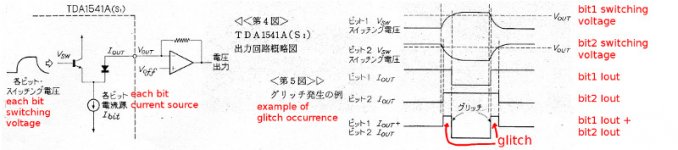
TDA1541A have diode-transistor switch to switch on or off bit current.
Thus their threshold voltage is affected by voltage of Iout pin node.(normally 0V)
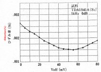
Hence, it may be able to trim switch timing to minimize glitch by trimming no signal voltage at Iout.
It is easy if the IVC is typical OPA-IV, add some offset voltage to noninverting input.
Nakamichi published the distortion at 1kHz 0dB signal is lowered about a half with this tweak.
Ref. 橋本秀夫 小日向肇 ,ナカミチ#1000DATのコンセプト-3,ラジオ技術, 1989年4月号 pp. 48-52
Although it was not my objective, I found a interesting tweak of TDA1541A that is employed in nakamichi 1000p, in its commentary article.
It is well known, a harmful mid scale glitch occurs when MSB and lower bit switches over.
Nakamichi have employed two new deglitching circuit in 1000p.(though not SHA)
One is too complexed to imitate,(patent US5034744)
but the other is easyly applicable DIY projects.
(though i don't know whether it is violation of something copyright or patent.)
TDA1541A have diode-transistor switch to switch on or off bit current.
Thus their threshold voltage is affected by voltage of Iout pin node.(normally 0V)
Hence, it may be able to trim switch timing to minimize glitch by trimming no signal voltage at Iout.
It is easy if the IVC is typical OPA-IV, add some offset voltage to noninverting input.
Nakamichi published the distortion at 1kHz 0dB signal is lowered about a half with this tweak.
Ref. 橋本秀夫 小日向肇 ,ナカミチ#1000DATのコンセプト-3,ラジオ技術, 1989年4月号 pp. 48-52
Attachments
- Home
- Source & Line
- Digital Line Level
- Building the ultimate NOS DAC using TDA1541A