Regarding your output filter, are you not concerned about phase shift impairments to sound?
Also, I'm a bit confused about the DEM capacitor. Does the value need to be such that it is a multiple of the sampling frequency? As long as it "locks" it is OK?
I'm referring to post #4598 where there was a discussion about using a 1nF which resulted in approximately 80KHz DEM frequency.
Thanks
Also, I'm a bit confused about the DEM capacitor. Does the value need to be such that it is a multiple of the sampling frequency? As long as it "locks" it is OK?
I'm referring to post #4598 where there was a discussion about using a 1nF which resulted in approximately 80KHz DEM frequency.
Thanks
Hi oshifis,
There can be a big difference between impressive and transparent sound. Impressive sound usually causes listening fatigue over time. Specific distortion can also sound impressive, one always has to be very careful not to mix-up impressive sounding distortion with transparent sound.
The DEM decoupling caps have a function, removing them can cause inconsistent performance (noise, low level distortion).
DEM decoupling is highly critical as GND noise and DC leakage currents can degrade performance.
Here is a possible solution, daisy-chain DEM decoupling (haven't tested this yet):
1uF cap between pins 7 & 8
1uF cap between pins 8 & 9
1uF cap between pins 9 & 10
1uF cap between pins 10 & 11
1uF cap between pins 11 & 12
1uF cap between pins 12 & 13
1uF cap between pin 13 & AGND (pin 5).
1uF cap between pins 24 & 23
1uF cap between pins 23 & 22
1uF cap between pins 22 & 21
1uF cap between pins 21 & 20
1uF cap between pins 20 & 19
1uF cap between pins 19 & 18
1uF cap between pin 18 & AGND (pin 5).
Decoupling values:
Bit 10, 143nF
Bit 11, 167nF
Bit 12, 200nF
Bit 13, 250nF
Bit 14, 333nF
Bit 15, 500nF
Bit 16, 1uF
Lowest bit decoupling still meets nominal value of 100nF. Injection of ground noise is greatly reduced, DC leakage current is greatly reduced.
It is also good practice to attenuate (switching) noise and mirror images (44K1, 88K2, 132K3, 176K4, 220K5 and so on) present at the DAC chip output.
I am currently experimenting with a 21 KHz Cauer-Pi low-pass filter with integrated 44K1 trap (parallel resonance circuit). Higher mirror frequencies will be handled by the low-pass function.
This filter is placed between DAC chip output and I/V stage input. The filter is loaded with approx. 13 Ohms (I/V stage input impedance). The Cauer filter is dimensioned such way that a trebles-boost is obtained by shaping the filter response.
This method can also be used with passive I/V conversion (I/V resistor on the DAC chip output), but the filter values have to be recalculated for the different load impedance (I/V resistor value).
here is an online calculator for Cauer Pi filters:
Chebyshev Pi LC Low Pass Filter Calculator
For 27 OHms I/V resistor (load impedance) for example one gets following values for 3 filter components: 289nF, 235uH, and 289nF.
It is important to use air core chokes.
The shunt capacitor value (44K1 trap) can be calculated with this LC series resonance calculator:
LC Resonance Frequency Calculator - Ekswai
The shunt capacitor for the 235uH choke would be 55.4nF.
The trap works as follows, at the tuning frequency of 44K1 the impedance of the parallel resonant circuit (235uH & 55.4nF) will rise significantly. This together with the relatively low load impedance (27 Ohms in the example) will result in extra attenuation of 44K1 (sample frequency).
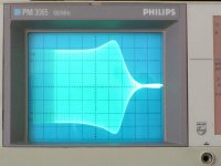
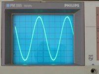
One can verify filter operation by using a 1 KHz test signal, it should look perfectly smooth without any visible steps on the oscilloscope.
One could experiment with I/V resistor value so the filter can be built using (combinations of) standard E12 values for caps and choke.
When the DEM oscillator timing cap has the correct value there should be a lock, however, due to drift (temperature) lock-out can occur over time. The jitter is quite normal with the datasheet app, performance can be optimised by using an un-interrupted ground plane and very small (805 size) film cap with shortest possible traces.
EMI pick-up can be greatly reduced by the following:
6K8 between pins 15 & 16
6K8 between pins 15 & 17
Timing cap between pins 16 & 17 (value has to be increased due to reduced oscillator input impedance).
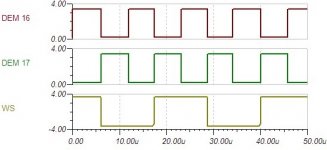
Attached picture of the DEM clock shows the typical DEM oscillator signal for this free running DEM clock.
The Cauer filter is dimensioned such way that a trebles-boost is obtained by shaping the filter response.
This method can also be used with passive I/V conversion (I/V resistor on the DAC chip output), but the filter values have to be recalculated for the different load impedance (I/V resistor value).
Hi EC,
may I ask what are your passive filter values for the treble boost before the I/V?
I have seen in another thread the need for "sin c correction" posted in a tube buffer implementation for the TDA1541A;
but these values (for a 4 dB boost at 20 khz) are for a 47 ohm passive I/V resistor and I use 100 ohm in that place;
so I wanted to ask maybe you have a better solution for a passive filter for my example of 100 ohm I/V resistor because this treble boost is very well needed in the case of NOS that I use
Thanks
An externally hosted image should be here but it was not working when we last tested it.
Hy lux
the week point in tube sch could be the value of the coupling cap
I am pointing this because I tested sound Q with respect to the value of the C
in Your case is 2.2uF
The sound is affected mainly with a higher values of this C
tested values was 2.2uF 4.7 to 10uF
Brands Duelund, Mundorf, Clarity, ERO, old PIO etc
R after the C was setted to the same low end bandwith...
...
Only the low values was giving a preferable outcomes
like 120nF/600V styroflex and 4 ll 47nF styro types
other low valued types work also better then higher values....
.
R after the C was 1Meg - 820K - 680K min.
.
So put some 0.1 to 0.12uF any type You find suitable in the very same SCH
leave 1meg after
AND ADD second section of the ECC88 like output, lover resistance buffer
in simple cathode follower in the same power dconsumption and adjust the same disipation on 2/2 section like in 1/2 section, which is not to be the catch
because Yu are using the choke load
...
this is a minor opperation but You will spot the diff
cheers
in ALL cases
Hi roger57,
Perceived sound quality is the most important factor, so far no audible "problems" with the Cauer filter plus 44K1 trap.
I tested a 3rd order Cauer-Pi filter with integrated parallel resonance circuit ( 9 Ohm load, single TDA1541A).
C1 = 470nF, L1 - 150uH, shunt cap, 100nF, C2 = 470nF, 4 parts in total.
I attached an oscillogram of a 800Hz … 88K2 sweep that shows filter response.
Second oscillogram shows the resulting 1 KHz sine wave test signal.
Another approach to the problem with mirror images is used by Zanden:
Analog filter for digital audio system and audio amplifier for using the same - Patent # 6721427 - PatentGenius
Analog filter for digital audio system and audio amplifier for using the same - Drawing for Patent # 6721427 - PatentGenius
Analog filter for digital audio system and audio amplifier for using the same - Drawing for Patent # 6721427 - PatentGenius
Here multiple notch filters are connected in series to attenuate 44K1 fundamental and its harmonics 88K2 … 220K5. If I am correct, and additional 88K2 low-pass filter is used to tackle large bandwidth RF noise that isn't attenuated by the cascaded notch filters.
The filter is rather complex and filter component properties will have impact on perceived sound quality. The filters are difficult to tune as well (component tolerances).
Technically the DEM frequency can be any practical value up to approx. 500 KHz. Above this frequency the effect of DEM switch settling time starts to cause too much degrading.
The main problem is on-chip crosstalk between the non-synchronised DEM clock and I2S timing signals that have impact on timing (jitter, noise). DEM decoupling capacitor RF properties then translate to different jitter spectrum. This in turn translates to different perceived sound quality. The ripple current on the bit currents is no problem as long as DEM decoupling cap value is high enough with regard to DEM frequency.
One way of reducing the effects of crosstalk is synchronising the DEM clock to fs or multiples of fs. This is rather difficult and practical circuits are often instable and produce inconsistent results. Other big problem is the additional clock load placed on masterclock / BCK that causes clearly audible degradation regardless of masterclock & clock distribution system.
Another method is lowering DEM frequency so its impact (crosstalk) will be barely audible as it falls outside the critical audio range. I already tested down to 40Hz using 3uF DEM oscillator timing cap and daisy-chained 330uF/16V decoupling caps. It is important to observe electrolytic capacitor polarity. When in doubt, simply measure the DC voltage on each pin and use this as reference for capacitor polarity.
Regarding your output filter, are you not concerned about phase shift impairments to sound?
Perceived sound quality is the most important factor, so far no audible "problems" with the Cauer filter plus 44K1 trap.
I tested a 3rd order Cauer-Pi filter with integrated parallel resonance circuit ( 9 Ohm load, single TDA1541A).
C1 = 470nF, L1 - 150uH, shunt cap, 100nF, C2 = 470nF, 4 parts in total.
I attached an oscillogram of a 800Hz … 88K2 sweep that shows filter response.
Second oscillogram shows the resulting 1 KHz sine wave test signal.
Another approach to the problem with mirror images is used by Zanden:
Analog filter for digital audio system and audio amplifier for using the same - Patent # 6721427 - PatentGenius
Analog filter for digital audio system and audio amplifier for using the same - Drawing for Patent # 6721427 - PatentGenius
Analog filter for digital audio system and audio amplifier for using the same - Drawing for Patent # 6721427 - PatentGenius
Here multiple notch filters are connected in series to attenuate 44K1 fundamental and its harmonics 88K2 … 220K5. If I am correct, and additional 88K2 low-pass filter is used to tackle large bandwidth RF noise that isn't attenuated by the cascaded notch filters.
The filter is rather complex and filter component properties will have impact on perceived sound quality. The filters are difficult to tune as well (component tolerances).
Also, I'm a bit confused about the DEM capacitor. Does the value need to be such that it is a multiple of the sampling frequency? As long as it "locks" it is OK?
Technically the DEM frequency can be any practical value up to approx. 500 KHz. Above this frequency the effect of DEM switch settling time starts to cause too much degrading.
The main problem is on-chip crosstalk between the non-synchronised DEM clock and I2S timing signals that have impact on timing (jitter, noise). DEM decoupling capacitor RF properties then translate to different jitter spectrum. This in turn translates to different perceived sound quality. The ripple current on the bit currents is no problem as long as DEM decoupling cap value is high enough with regard to DEM frequency.
One way of reducing the effects of crosstalk is synchronising the DEM clock to fs or multiples of fs. This is rather difficult and practical circuits are often instable and produce inconsistent results. Other big problem is the additional clock load placed on masterclock / BCK that causes clearly audible degradation regardless of masterclock & clock distribution system.
Another method is lowering DEM frequency so its impact (crosstalk) will be barely audible as it falls outside the critical audio range. I already tested down to 40Hz using 3uF DEM oscillator timing cap and daisy-chained 330uF/16V decoupling caps. It is important to observe electrolytic capacitor polarity. When in doubt, simply measure the DC voltage on each pin and use this as reference for capacitor polarity.
Attachments
Last edited:
Hi roger57,
Perceived sound quality is the most important factor, so far no audible "problems" with the Cauer filter plus 44K1 trap.
Agreed. Beauty is in the ears of the listener...the perception
Technically the DEM frequency can be any practical value up to approx. 500 KHz. Above this frequency the effect of DEM switch settling time starts to cause too much degrading.
The main problem is on-chip crosstalk between the non-synchronised DEM clock and I2S timing signals that have impact on timing (jitter, noise). DEM decoupling capacitor RF properties then translate to different jitter spectrum. This in turn translates to different perceived sound quality. The ripple current on the bit currents is no problem as long as DEM decoupling cap value is high enough with regard to DEM frequency.
One way of reducing the effects of crosstalk is synchronising the DEM clock to fs or multiples of fs. This is rather difficult and practical circuits are often instable and produce inconsistent results. Other big problem is the additional clock load placed on masterclock / BCK that causes clearly audible degradation regardless of masterclock & clock distribution system.
Another method is lowering DEM frequency so its impact (crosstalk) will be barely audible as it falls outside the critical audio range. I already tested down to 40Hz using 3uF DEM oscillator timing cap and daisy-chained 330uF/16V decoupling caps. It is important to observe electrolytic capacitor polarity. When in doubt, simply measure the DC voltage on each pin and use this as reference for capacitor polarity.
In another thread in DIY Audio, someone posted an paper by Henk ten Pierick for synchronizing the WS to couple the DEM. Did you ever try this, and if so, you must have abandoned it for one reason or another?
Thanks
Gary
Hi maxlorenz,
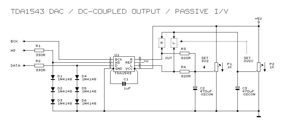
TDA1543 output circuit is different from TDA1541A and needs no current buffer.
I attached schematic of a TDA1543 DAC with DC-coupled outputs and passive I/V conversion.
This is the best performing (and easiest to build) TDA1543 circuit I designed so far (tested on MK9 prototype setup with latest timing module).
R1, R2, D1 ... D6 are WS / DATA limiters (1.8Vpp).
C1 is a 1uF 1210 SMD film cap soldered directly to TDA1543 pins 4 and 5 as close to the plastic housing as possible.
R3 and R4 are passive I/V resistors that offer approx. 0.0025 * 820 = 2.05Vpp output signal.
P1 is passive I/V resistor bias voltage (adjust to 3.2V).
P2 provides DC-coupled outputs (no coupling cap required). Adjust P2 for lowest DC offset on R and L outputs. This would give around 2.2V on the wiper of P2.
TDA1543 requires a super clean 5V power supply (balanced or battery power supply) and ultra low jitter BCK signal with white noise residual jitter spectrum.
/QUOTE]
hi, help me understand this genius circuit, please. i tried this build a while ago and could not get p1/p2 to stabilize. i forget the values but if i adjusted p1, p2 would drift and vise versa.
i'd like to try this beaut again in differential mode.
Last edited:
")
Perceived sound quality is the most important factor, so far no audible "problems" with the Cauer filter plus 44K1 trap.
I tested a 3rd order Cauer-Pi filter with integrated parallel resonance circuit ( 9 Ohm load, single TDA1541A).
C1 = 470nF, L1 - 150uH, shunt cap, 100nF, C2 = 470nF, 4 parts in total.
...
Hello ecdesigns
About your Cauer Pi filters, for 27 OHms I/V resistor (load impedance)
What sound differences between those values: C1 = 289nF, L1 - 235uH, shunt cap, 289nF, C2 = 289nF.
and C1 = 470nF, L1 - 150uH, shunt cap, 100nF, C2 = 470nF ?
Thank you
Bye
Gaetan
In another thread in DIY Audio, someone posted an paper by Henk ten Pierick for synchronizing the WS to couple the DEM. Did you ever try this, and if so, you must have abandoned it for one reason or another?
Thanks
Gary
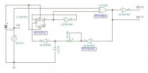
The following could be a way to run the DEM at 88k2 in synchro with WS, using Potato TTL gates.
At this moment I have no chance to give it a try.
Seems most people prefer the free running DEM, anyone did never tried such kind of synchronizing?
Attachments
Hi, -ecdesigns-!
At such a low frequency DEM mechanism stops working. Then it is better to just turn off it, because of him there is no sense.
Each current divider will supply current for 25 ms. During this time will change 44.1 * 1000 * 25/1000 = 1102 samples. For these 1102 samples a reference current generated by the same current divider. That is, for them the mechanism of DEM as to be no.
I already tested down to 40Hz using 3uF DEM oscillator timing cap...
At such a low frequency DEM mechanism stops working. Then it is better to just turn off it, because of him there is no sense.
Each current divider will supply current for 25 ms. During this time will change 44.1 * 1000 * 25/1000 = 1102 samples. For these 1102 samples a reference current generated by the same current divider. That is, for them the mechanism of DEM as to be no.
This is true if no external filter capacitor is used. A large enough external capacitor will filter the ripple, that is it will average the current of the four current dividers. In my opinion it does make sense to go low with the DEM frequency, because it is easier to get exact 50% duty cycle.
Hi, oshifis!
An external capacitor is not a substitute for DEM. The problem here is not the current ripple. With DEM mechanism achieved averaging DC (reference current) from four current sources. Capacitor dont make this averaging, since it does not run on direct current.
This is true if no external filter capacitor is used. A large enough external capacitor will filter the ripple, that is it will average the current of the four current dividers.
An external capacitor is not a substitute for DEM. The problem here is not the current ripple. With DEM mechanism achieved averaging DC (reference current) from four current sources. Capacitor dont make this averaging, since it does not run on direct current.
Hi, oshifis!
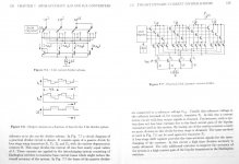
The term "averaging" reflects the essence of the DEM mechanism. Bit currents of neighboring bits should be different exactly twice. DEM mechanism achieves this by interchanging reference currents, which leads to an time averaging of the reference currents. Read the monograph van de Plassche. I already gave a link to it. Here is an excerpt from chapter 7 of this monograph.
The term "averaging" reflects the essence of the DEM mechanism. Bit currents of neighboring bits should be different exactly twice. DEM mechanism achieves this by interchanging reference currents, which leads to an time averaging of the reference currents. Read the monograph van de Plassche. I already gave a link to it. Here is an excerpt from chapter 7 of this monograph.
Attachments
Interesting article, thanks. Also worth reading "Dynamic Element Matching for High-Accuracy Monolythic D/A Converters" in the IEEE Journal of Solid-State Circuits, Vol. SC-11, No. 6, December 1976.
BTW I read several times that the different DEM filtering capacitors make different sound. One of my friends swears on Black Gate NX Hi-Q, others to Elna Silmic. It is beyond me what could cause the sonic difference. Anybody could explain it?
BTW I read several times that the different DEM filtering capacitors make different sound. One of my friends swears on Black Gate NX Hi-Q, others to Elna Silmic. It is beyond me what could cause the sonic difference. Anybody could explain it?
- Home
- Source & Line
- Digital Line Level
- Building the ultimate NOS DAC using TDA1541A