wavebourne #
Going back to the first schematic of the power amp psu, I notice you have no current limiting on the output i.e output Z is quite high and have to slug Low esr into a 470uF o/p relying on the 22R series resistor to take the surge up. On start up this is going to stew ?
As I see it, you are relying on the o/p cap (470uF) to keep psu ripple down, whereas if you split R1 i.e 10K then 47K and at the junction put a 22uF electroytic you will get another 40dB better ripple rejection and can reduce the value of the o/p cap.
Jay or nay ?
richj
richwalters said:wavebourne #
Going back to the first schematic of the power amp psu, I notice you have no current limiting on the output i.e output Z is quite high and have to slug Low esr into a 470uF o/p relying on the 22R series resistor to take the surge up. On start up this is going to stew ?
As I see it, you are relying on the o/p cap (470uF) to keep psu ripple down, whereas if you split R1 i.e 10K then 47K and at the junction put a 22uF electroytic you will get another 40dB better ripple rejection and can reduce the value of the o/p cap.
Jay or nay ?
richj
1. I am relying on a resistor and Zener. Output Z is quite low because of feedback by voltage.
2. A gas discharge tube has more then zero dynamic resistance, so ripples are applied to both destination and source in the same polarity.
However, I can put an electrolytic there; also I can replace the resistor by a CCS, but what for? Also, I could use an opamp instead of a single FET, but actually I don't need more regulation.
3. I went with a simpler version, adding couple of Zeners in series with gas discharge tube, and using a single source follower, without any error amp. More than plenty of regulation as the result using much less of parts.
So, this one was as some people say, "Over-Engineered", I would call "Suboptimal".
There are some sellers of GU50 in Europe, try these:
Röhrentechnik
Frag Jan Zuerst Welter Electronic
Audiotriodes
Röhrentechnik
Frag Jan Zuerst Welter Electronic
Audiotriodes
Wavebourn said:Here is phase splitter schematics. Comments/suggestions?
This had changes as well:
R8 is 3 resistors 56K each in parallel, R10 and R11 -- both have 2 resistors 56K in parallel.
The second tube is 6N6P instead of 6N1P
soundbrigade said:Wavebourne: I recall that you used something like 700V on the GU50. Would this splitter work with the OP-stage configured differently (lower high tension other anode load)?
I use the same to drive 6L6 tubes with 375V on plates.
Altec as I said before used very similar one in their 1568 and 1569 amps, it may be viewed as a Williamson phase splitter, but without one RC coupling network for better stability on low end.
IMHO one should keep audio amp all tubes, including the G2 supply. The RC-31 has a great G2 regulator. Easiest thing to do is the Altec 6146 amp and run a shunt regulator with a couple gas tubes. Sure the solid-state designs are higher performance but may as well build the entire amp solid state then. I probably know Mr Waveborne either from those Randall Museum meets or the Bay Area Tube Club before that. BTW I usually prefer to run Paraphase inverters...unless of course my project is an SE design.
Last edited:
IMHO one should keep audio amp all tubes, including the G2 supply. The RC-31 has a great G2 regulator. Easiest thing to do is the Altec 6146 amp and run a shunt regulator with a couple gas tubes. Sure the solid-state designs are higher performance but may as well build the entire amp solid state then.
Similarly, "one should keep an amp resistor-only, no capacitors nor inductors added".
SS assisted tube amps is a new fashion for High-End. However, their designers should know well both SS and vacuum components, otherwise pity hybrids are made that are worse sounding than either SS or tube amps...
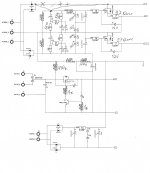
Here is PS from Pyramid-VII amps:
Attachments
Last edited:
Thanks for the schematic post. Very nice. I am not knocking your work; actually I am sure that it sounds great. Otherwise why bother?
Couple comments though. The original amplifiers had only tubes and transformers; R-C coupled amps came out later when higher mu triodes were developed. And amps having only glass and iron in the signal path can sound very good indeed. They will be zero feedback so you had better know what you are doing.
In many cases the SS electronics are very appropriate, particularly for filament and bridge rectifier applications.
That having been said though my take on your circuit would be to at least run the more stable gas regulators in place of the avalanche diodes and also a damper tube on the bridge output would provide a soft startup.
Thank you! But...
Why should I need softer startup? It is soft enough to me.
If I needed softer, I would increase values of capacitors in reference voltage stabilizers, or implemented positive feedback by current. I used positive feedback by current when needed soft startup, the voltage regulator waited for the load to start drawing current, then was bringing it up faster. It waited for tubes to heat up and start drawing current.
Couple comments though. The original amplifiers had only tubes and transformers; R-C coupled amps came out later when higher mu triodes were developed. And amps having only glass and iron in the signal path can sound very good indeed. They will be zero feedback so you had better know what you are doing.
I dig transformer coupling, and love those old Thorardson and WE amps. But was it really b/c of the low mu tubes they used ITs?
Why do you need know what your doing any more with zero NFB amps than those with loop NFB? I'd think it's the other way around since you easily get problems with phase and BW (same coin I guess) and that requires attention to detail...???
To Wavebourne: Hey different strokes. My tastes, situation, etc are different and of course I heed that bumper sticker from Vacuum Tube Valley 'Use a Transistor Go to Jail'
To the contributor re the zero FB designs. A good sounding zero FB design requires a great deal of expertise. They are very unforgiving; achieving good damping factor, low distortion, and reasonable power output is not trivial. The amp that I listen to is of course a zero FB design. Yes it has a SS diode rectifier for the B+ and bias supplies. http://www.diyaudio.com/forums/images/smilies/cool.gif
My GU-50 amp is being built on a nice 'Welbourne Labs' chassis that I got from EBAY. The sockets fit the slow start Russian rectifier as well as the GU-50's. Power is provided by a Baldwin power trannie; a set of Mesa Strategy 400 OPTs couple the GU-50s to the speakers. I plan on doing a study on the GU-50s with my DOS-based SOFIA prior to setting up the G2 bias circuit.
That amp was initially designed as class AB amp, so zero FB was not an option. For zero FB class A is needed. But for class A I prefer single ended topology. And great deal of experience is needed for any design, be it zero FB, or a lot of FB. The man goal in both cases is clean sound, the difference is allowed power dissipation per sound pressure.
A totally different topic...
A totally different topic...
@Wavebourn
Do you want to post the entire schematics?
Here is the output stage:
Attachments
Thanx. I will post my GU-50 amp as soon as I plot it. On the zero FB front; the Radiotronics guide suggests push-pull low mu triodes. I like cathode follower SE driven by plate loaded triode.
Hi Dave, did you plot it?
Just curious...
Hi Dave, did you plot it?
Just curious...
That amp build is in the queue (a SE 6S33S and a solid-state HF amp on the bench right now); I did just get some '72 vintage GU50's with the holder type sockets from Lithuania; so I should be able to run curves on my SOFIA shortly.
That amp build is in the queue (a SE 6S33S and a solid-state HF amp on the bench right now); I did just get some '72 vintage GU50's with the holder type sockets from Lithuania; so I should be able to run curves on my SOFIA shortly.
Wow!
Can you help me to run curves for 6С17К tubes?
- Status
- This old topic is closed. If you want to reopen this topic, contact a moderator using the "Report Post" button.
- Home
- Amplifiers
- Tubes / Valves
- Building new GU-50 stereo amp...