The lat Fets require a much larger swing due to their lower transconductance.I just made a sim by drop in replacement of IRFP with a 2sk1056 model. It works but distortion level is 10 times higher. Maybe it requires a pre driver stage.
This forces the VAS into large signal/class B and increased distortion.
I see no simple and elegant fix (for the time being)
2SK1530?
Thank you Elvee, this information is fair enough. At least there is 2SK1530 for who want to use an audio purpose FET but I'm not certain about it either. Cordell Audio model gives good THD results but current drawn by bias servo is getting a bit lower. Some people say it is lateral and other people say it is an audio purpose vertical mosfet. Could you comment on this device in an appropriate time please?
Circlophone is a spot on amplifier for mosfets because of using of same type device at output. Thus, mosfet lovers won't suffer by asymmetrical behavior of complementary designs.
Thank you.
The lat Fets require a much larger swing due to their lower transconductance.
This forces the VAS into large signal/class B and increased distortion.
I see no simple and elegant fix (for the time being)
Thank you Elvee, this information is fair enough. At least there is 2SK1530 for who want to use an audio purpose FET but I'm not certain about it either. Cordell Audio model gives good THD results but current drawn by bias servo is getting a bit lower. Some people say it is lateral and other people say it is an audio purpose vertical mosfet. Could you comment on this device in an appropriate time please?
Circlophone is a spot on amplifier for mosfets because of using of same type device at output. Thus, mosfet lovers won't suffer by asymmetrical behavior of complementary designs.
Thank you.
Code:
* 2SK1530C VDMOS  copyright Cordell Audio December 6, 2010
.model 2SK1530C VDMOS(nchan Vto=1.55 Kp=9.0 Lambda=0.002 Rs=0.025 Rd=0.1 Rds=1e7 Cgdmax=1500p Cgdmin=15p a=0.33 Cgs=880p Cjo=1260p m=0.68 VJ=2.5 IS=4.0E-06 N=2.4)
Last edited:
Hello everyone!
After multiple checks and apparently no errors, here is the final version of my circuit design.
I will now proceed to completion.
Regards!
Looking great Project16!
..just one thing you can also put an additional footprint as option for use with TO-220AC device for D4 & D5 (example MBR735).
Regards!
BC5XX version PCB files
Hello All,
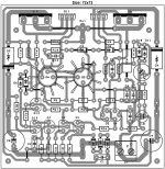
I want to share my latest versions of my pcb files. These are highly modified versions of Powerflux's very early work. Thanks for him/her to giving the idea of small size compact pcb layout. I begin to modify supply rail traces due to proper current flow over bypass caps and I'm here now.
I built this version with slightly different layout. First times I was a bit skeptic about using super fast and very low output capacitance devices at bias servo and I installed BD140's at first. Later, I decided to try a high voltage video transistor. Then I fitted 2SA1546's (fT=300Mhz, Cob=3.3pF, Vce=250V) in place of BD's. I didn't observe any negative effect on o'scope (though my limited measurement tools and skills) despite even faster Sanken MN2488's at output. But the difference in sound characteristic is easily noticeable: capturing nice details and delicate high frequency response. So, I don't hesitate to suggest you to trying this kind of devices at servo section.
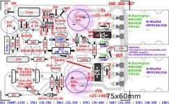
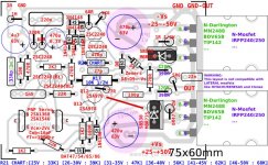
You can use power mosfets (non lateral type) or darlington power transistors at output. Mosfets must be matched due to their manufacturing dispersion comparing to Bjt's. Some components(330p/1n , 390R/120R) vary according to output device preference. I showed them in different color (Green=BJT Darlington, Purple=Mosfet). Red colored parts/sections are common.
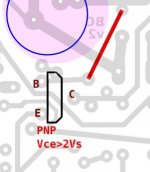
This layout uses BC type small transistors. I gave maximum 40V supply voltage rating (Vs) to this layout due to BC550C's max. 45V Vce rating. Q13 (indicated in layout) must have greater than 2*Vs (2*40V=80V in this case) Vce rating. Thus, I didn't place there BC type small transistor due to their max 65V Vce specification. Since that 2N type small signal transitors leg arrangement is compatible with BC types just by flipping 180 degree (side by side), I showed 2N5401's as Q12 and Q13. Q12 preferably must have same type as Q13 despite its lower Vce requirement.
R17, the main feedback resistor's default value is 10K, as shown in original schematic of Circlophone. Voltage gain setting is 10K/470=~22. You can adjust (probably increase) R17's value according your source voltage level and supply voltage limits.
R21 is a dummy CCS at 1-1.5mA. Its value varies according to Vs. I attached a simple chart showing corresponding R21 value depending supply voltage.
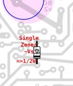
There are three different installation preferences of zeners on this layout. Two zeners option showed in default layout. I'm showing other options separately.
* Two zeners (as in original schematic) which totals around Vs
* One -at least- 1/2W zener rated around Vs
* Zenerless (Using an extra transistor which similar with the one at servo section)
In next post, I will share Japanese small transistor version.
Hope you enjoy.
Hello All,
I want to share my latest versions of my pcb files. These are highly modified versions of Powerflux's very early work. Thanks for him/her to giving the idea of small size compact pcb layout. I begin to modify supply rail traces due to proper current flow over bypass caps and I'm here now.
I built this version with slightly different layout. First times I was a bit skeptic about using super fast and very low output capacitance devices at bias servo and I installed BD140's at first. Later, I decided to try a high voltage video transistor. Then I fitted 2SA1546's (fT=300Mhz, Cob=3.3pF, Vce=250V) in place of BD's. I didn't observe any negative effect on o'scope (though my limited measurement tools and skills) despite even faster Sanken MN2488's at output. But the difference in sound characteristic is easily noticeable: capturing nice details and delicate high frequency response. So, I don't hesitate to suggest you to trying this kind of devices at servo section.
You can use power mosfets (non lateral type) or darlington power transistors at output. Mosfets must be matched due to their manufacturing dispersion comparing to Bjt's. Some components(330p/1n , 390R/120R) vary according to output device preference. I showed them in different color (Green=BJT Darlington, Purple=Mosfet). Red colored parts/sections are common.
This layout uses BC type small transistors. I gave maximum 40V supply voltage rating (Vs) to this layout due to BC550C's max. 45V Vce rating. Q13 (indicated in layout) must have greater than 2*Vs (2*40V=80V in this case) Vce rating. Thus, I didn't place there BC type small transistor due to their max 65V Vce specification. Since that 2N type small signal transitors leg arrangement is compatible with BC types just by flipping 180 degree (side by side), I showed 2N5401's as Q12 and Q13. Q12 preferably must have same type as Q13 despite its lower Vce requirement.
R17, the main feedback resistor's default value is 10K, as shown in original schematic of Circlophone. Voltage gain setting is 10K/470=~22. You can adjust (probably increase) R17's value according your source voltage level and supply voltage limits.
R21 is a dummy CCS at 1-1.5mA. Its value varies according to Vs. I attached a simple chart showing corresponding R21 value depending supply voltage.
There are three different installation preferences of zeners on this layout. Two zeners option showed in default layout. I'm showing other options separately.
* Two zeners (as in original schematic) which totals around Vs
* One -at least- 1/2W zener rated around Vs
* Zenerless (Using an extra transistor which similar with the one at servo section)
In next post, I will share Japanese small transistor version.
Hope you enjoy.
Attachments
Japanese small transistor version
Hello All,
As I mentioned previous post, I'm sharing latest version of Japanese small transistor version of my layout.
I showed max. 50V supply voltage due to these small transistors' acceptable Vce ratings.
I showed 2SC2240/2SA970's from Toshiba. But you can choose other options like 2SC/KSC1845 - 2SA/KSA992 pairs. Q12 and Q13 maybe must have chosen from slightly higher wattage versions (like 2SA1145) for supplies above 40V.
Other comments can be applied same as previous layout (including zener option preference).
Hope you enjoy.
Attachments
Oh, wow. Awesome. Post 1 has been updated to include your Mosfet amp.
Thank you Daniel. I think that list going to be grow easily by flexible nature of Circlophone topology. There are many alternatives, many preferences. Hope you find one that meets your high power requirements.
Last edited:


Terranigma,
I'm curious if you'd consider integrating Keantoken's darlington input buffer on your darlington output amplifier? Kean's buffer has an extremely low insertion loss and low parts count, and it fits easily right onto the input pair, which is an elegantly streamlined integration. And, buffers are a "safe bet" for level sounding response despite source device variances; so, buffers can remove/reduce confusing fine fine tuning labors. I believe that Kean's buffer represents a small effort for a huge enhancement. Would you try it?
I'm curious if you'd consider integrating Keantoken's darlington input buffer on your darlington output amplifier? Kean's buffer has an extremely low insertion loss and low parts count, and it fits easily right onto the input pair, which is an elegantly streamlined integration. And, buffers are a "safe bet" for level sounding response despite source device variances; so, buffers can remove/reduce confusing fine fine tuning labors. I believe that Kean's buffer represents a small effort for a huge enhancement. Would you try it?
Hello everyone!
I finished the implementation of Circlophone but I have a question for the resistor R21.
my power supply is not stabilized and delivers +/- 27.5V.
For zener diodes D8 and D9 is ok but for the resistor R21 which is the method of calculation, I thought a 33k (speaker 8ohms).
Thank you!
I finished the implementation of Circlophone but I have a question for the resistor R21.
my power supply is not stabilized and delivers +/- 27.5V.
For zener diodes D8 and D9 is ok but for the resistor R21 which is the method of calculation, I thought a 33k (speaker 8ohms).
Thank you!
Terranigma thank you!
Regards!
I looked but I have difficulty finding the correct value.You can refer to Daniel's sizing chart on the schematic at first post of this thread.
Regards!
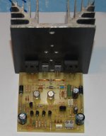
Hello Project16, it looks very nice and tidy! Did you insert a bulb tester to mains before first run? You can estimate the excessive current drawn by amplifier with observing bulb's light level.
You can measure voltage the between the legs of the 1ohm resistor. You must read between 150-200 mV (which means 150-200mA quiescent current) if your amplifier is healthy.
BTW, I see you used 2n3440's as bias servo. Semelab and ST datasheet says that this is a (minimum) 15Mhz device. Which is is not a good sign for being a servo transistor.
Last edited:
I measure 196 mv.You can measure voltage the between the legs of the 1ohm resistor. You must read between 150-200 mV (which means 150-200mA quiescent current) if your amplifier is healthy.
But I have no output load (speaker).
Regards!
Project16,
In regards to the diagram attached to post 221, if you put a good size via (hole, vent) exactly where it is marked "Q5" and another at "Q6" those transistors will create their own breeze to help cooling. Hot air wants to go up so if there's a vent underneath Q5 and Q6, then cool air will enter at underneath the transistors and cause air movement. That prevents heat pooling.
The same concept is true of almost any size heatsink--needs air intake underneath it to make it work.
- Home
- Amplifiers
- Solid State
- Building Elvee's Circlophone: Documentation, Parts, Accessories, & beginner friendly