Any problem with it?
Is it 50VA? I don't think that it will sag if so. If it is the R-Core from France, its going to be more than VAC nominal.

A bit puzzled
I haven't written anything about my results with the DCB1 build for a while due to some unexpected results. Meaning that the frequency response is very different from the NAD C160 that this is intended to replace. In comparison the high frequency response is rolling off for reasons unknown to me as of yet.
Since I had bought one of the B1 kits off of eBay I went ahead and built that to compare it to. The results are pretty similar in that the frequency response is out of balance starting somewhere in the higher mid-range. I'm not sure what to make of this yet but am going to make a passive 50K volume control to see if this sheds some light on what is happening. I am not sure that this would be due to a poor mach between components. The B1 and the DCB1 are being driven by a Musical Fidelity A324 (output impedance of 50 Ohms) and are driving a Marchand XM-9 (input impedance of 25K). I may be able to acquire an oscilloscope later this week and perhaps that will be of some help.
I still have high hopes for this pre-amp and am not going to give up on it quite so easily. I have almost exactly the sound that I was looking for with my current stereo but felt that it was time to simplify the electronics as much as possible.
On a positive note, however, I can say the depth of the soundstage is very promising with the DCB1.
Last edited:
How is it driven? Is there a pot before it? If yes, what value? What is the droop you have measured? -dB? Freq? Don't put more than 20k-25k pot.
Disaster scenario Sci-Fi:
Are your gate stopper resistors for the audio fets 220R and not much bigger by mistake? Can there be the 220k in series and the 220R shunt? That could create filters.
Disaster scenario Sci-Fi:
Are your gate stopper resistors for the audio fets 220R and not much bigger by mistake? Can there be the 220k in series and the 220R shunt? That could create filters.
How is it driven? Is there a pot before it? If yes, what value? What is the droop you have measured? -dB? Freq? Don't put more than 20k-25k pot.
Disaster scenario Sci-Fi:
Are your gate stopper resistors for the audio fets 220R and not much bigger by mistake? Can there be the 220k in series and the 220R shunt? That could create filters.
It is being driven by a DAC with a 50 Ohm output impedance.
I do not have a way to measure the frequency response. As best as I can describe it is the bass through low midrange is louder than the midrange through the treble. I would guess between 6 to 10 db difference between the bass and treble.
You might have identified the problem. I am using a 50K Ohm stereo potentiometer. I used the same pot on both the DCB1 and the B1 so that could very well be the mismatch. I do have a 20K pot ordered and should be able to try that soon. I checked the gate stoppers and they are carbon film, 220 Ohm resistors that I got from Mouser. I haven't attempted to use the LDR's yet because I felt more comfortable starting with a simpler volume pot, first. That and I had not ordered the power supply parts to run the Lightspeed attenuator.
Thank you for the advice. I'll check back in when I get the new pot.
50k pot can make it ''slower'' but not droop it anywhere near the audio band.
I just measured for you a Mez build I got here with 20k pot. It was connected to the amp as I was measuring from a parallel output. 176.4kHz rate 1/96 octave band pink shows just my Emu's filter shape 88kHz limit with the DCB1 in the loop. 48kHz 1/12 added to see the lows too. There is something else wrong in your system most probably.
P.S. THD+IMD merged plots 0dB=1VRMS top, 160dB window.
Attachments
What's the reason for preferring carbon for the 470R resistors? I've got some 1/2w PRPs, would it be a problem to use those instead?
Carbon composition has no parasitic inductance, is preferable for such uses in general, but with 470R and IRFPs Ciss there will be no practical problem using the PRPs.
I have already finished assembling my LDR volume and integrating it with my DCB1. I have mad the capacitor mod too (I had already upped the CCS). I have put a pair of 0,1uF Orange drop polypropilene (715P10452LD3 Vishay/Sprague Polypropylene Film Capacitors)
I will let burn in the whole thing and tell you my listening results in a few days. I will make some RMAA tests too
I will let burn in the whole thing and tell you my listening results in a few days. I will make some RMAA tests too
50k pot can make it ''slower'' but not droop it anywhere near the audio band.
I just measured for you a Mez build I got here with 20k pot. It was connected to the amp as I was measuring from a parallel output. 176.4kHz rate 1/96 octave band pink shows just my Emu's filter shape 88kHz limit with the DCB1 in the loop. 48kHz 1/12 added to see the lows too. There is something else wrong in your system most probably.
P.S. THD+IMD merged plots 0dB=1VRMS top, 160dB window.
Salas, Thank you for your help.
Perhaps I need to carefully compare the BOM to the parts that I used. I did substitute a few of the parts because Mouser was out of the recommended ones. I thought I had chosen safe substitutes but perhaps the error is there. Somehow I have made a high frequency attenuator at some point in this circuit. If I learn something from a mistake then that is OK. This is the first DIY component I have attempted that was not a preassembled kit. I may have made a mistake chosing an alternate part. I believe that the FET's are right for this pre-amp unless they are fakes. I don't think this is the problem, though.
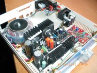
I have finished my DCB1 and placed it in a definitive enclosure. I have changed the internal arrangement to place the transformer far away from the LDR volume control. The LDRs have its own psu separated from the preamp, but feeded from the main filter capacitors of the DCB1.
I changed the bypass caps for two 0.1uF Orange drops. CCS resistor is 10 ohms 5W. Wiring is Cat5e and the enclosure is from an old telecom equipment.
I will make some RMAA measurements and post them soon.
Enjoy it,
Regards,
Regi
I changed the bypass caps for two 0.1uF Orange drops. CCS resistor is 10 ohms 5W. Wiring is Cat5e and the enclosure is from an old telecom equipment.
I will make some RMAA measurements and post them soon.
Enjoy it,
Regards,
Regi
Attachments
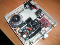
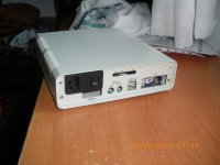
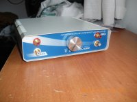
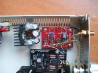
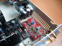
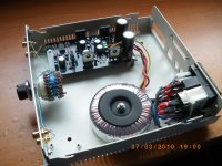
I have finished my DCB1 and placed it in a definitive enclosure. I have changed the internal arrangement to place the transformer far away from the LDR volume control. The LDRs have its own psu separated from the preamp, but feeded from the main filter capacitors of the DCB1.
I changed the bypass caps for two 0.1uF Orange drops. CCS resistor is 10 ohms 5W. Wiring is Cat5e and the enclosure is from an old telecom equipment.
I will make some RMAA measurements and post them soon.
Enjoy it,
Regards,
Regi
awesome piece of kit!
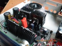
Yeah, it is the same buffer I had before but with the capacitor mod and the LDR volume control. It is the same enclosure but with a different arrangement. Attached is how it was some days ago, with the cheapo switcher.
I really like the sound of this amp. I cannot be sure about the changes because I have changed my loudspeakers recently. But it sure is a better volume control with no contact point issues. The cheap one used to fail from time to time.
Regards,
Regi
I really like the sound of this amp. I cannot be sure about the changes because I have changed my loudspeakers recently. But it sure is a better volume control with no contact point issues. The cheap one used to fail from time to time.
Regards,
Regi
Attachments
- Home
- Amplifiers
- Pass Labs
- Building a symmetrical PSU B1 buffer