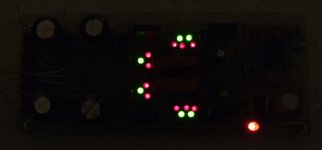
The jfets working under Vbe only which form the string of five constant current drains lost 25-30% IDSS VS battery test. Hence the leds lost a bit of Vf each is the voltages explanation. Very good voltages as for DCB1, no further tweaks are needed.
If you will mutually swap the 3mV pair jfets there can be a different result for better or worse. But 3mV is mighty fine. You gonna put an all DC scenarios safety capacitor in the output as you said, so any DC becomes a non issue anyway. Happy listening.
If you will mutually swap the 3mV pair jfets there can be a different result for better or worse. But 3mV is mighty fine. You gonna put an all DC scenarios safety capacitor in the output as you said, so any DC becomes a non issue anyway. Happy listening.
Thanks for your suggestion, but the problem is also with other interconnects, see Post #2458 . A bit better but not silent...
Still, have a look at what I try to say:

[I had this similar problem too when I went from 330B mono's to Le Monstre]
It is these two sides of the loop (L/R) that have to be twisted or taped together.
The output impedance of the B1 is not low enough to kill the inductance . . . completely. (A Kondo stage would do slightly better probably)
albert
Still, have a look at what I try to say:
View attachment 268244
[I had this similar problem too when I went from 330B mono's to Le Monstre]
It is these two sides of the loop (L/R) that have to be twisted or taped together.
The output impedance of the B1 is not low enough to kill the inductance . . . completely. (A Kondo stage would do slightly better probably)
albert
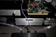
Hi Albert,
i tried that. A bit better like the Nordost cables i had tried, but the hum is still there...
Attachments
I'm sorry to say it but I prefer the sound of my B1 clone over that of the DCB1.
I might try the B1 with the SALAS reg to see if it improves matters.
For some reason or other my DCB1 just doesn't sound as "Clean" as the B1.
Before anyone comments, do remember that mine have both got output caps. I've used Mundorf 33uF630V Polyprops with the DCB1 and Obbligato 10uF PIOs with the B1.
My DCB1 is also single sided PCB whereas the B1 is double sided.
PLEASE NOTE - This is NOT a SALAS PCB, it is a homebrew board built using the original artwork.
I've also got very slight HUM which is not present on the B1, this could be down to layout or a faulty component.
One channel is distorting but only as I approach half volume.
Last edited:
Before I give up I'm going to have a careful check around the relay circuitry as there is an annoying turn ON "Thump" that definitely shouldn't be there with the relay in circuit.
SALAS suggested that the ouputs be grounded by the relay until the relay switches, this has been implemented.
SALAS suggested that the ouputs be grounded by the relay until the relay switches, this has been implemented.
One channel is distorting but only as I approach half volume.
Problem.
I know there's a problem.
Any suggestions what to measure and where ?
Funny thing is that it's OK at low level - either that or I can't hear the problem at low level.
Scope, FFT.
I've got rid of the distortion.
On my Home Brew PCB the traces around the relay are extremely close together and although I checked for copper whiskers, I think one crept back when I was soldering.
I will need to increase Turn ON delay though.
I've still got DC on the output (all-be-it mV) even with the N.O. contacts of the relay grounded so-as to short the outputs to ground.
Last edited:
You set it to AC input and you watch for oscillations or noise fuzz on the rails. Watch the probe's and scope's max voltage spec when doing tubes.
For some reason i thought it would be more complicared than that.
- Home
- Amplifiers
- Pass Labs
- Building a symmetrical PSU B1 buffer