- you must oversize the bootstrap capacitors to handle extra supply current from the buffer
Yes i know, i was thinking somewhere between 10-22uF values,i will experiment on this latter. Now i'm still working on the design schematic
That skiped me- output filter should also have capacitors to ground to kill common mode ripple (you filter only differential mode here). Don't let speaker cable to become an antenna
Btw guys, dont you know some links about class D feedback design? Don't get me worng here, i don't one none of you doing my homework but i need a bit push from the back with some infos...
If something on the outputstage goes wrong, i dont want to blow-up the intire board- why do you want an optocoupler?
i found out a document that in my opinion shares some light uppon my situation
here is this document: http://users.ece.gatech.edu/~mleach/...01/ClassD2.pdf
This is about a pre-filter feedback. This way you can't achieve a load-independent freq. response.
dont you know some links about class D feedback design?
I don't, but control theory is the same for Class D. I've told what you should do.
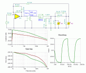
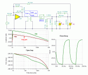
Pafi, can you please say (maybe even approximately), how deep will be the negative feedback in your example at 10KHz ?
Thanks, Pafi!
EDIT: Oh, I see now... R7 has the same value as R5, so VM2 has the same effect in closed loop, as an VG1 source in open loop...
Last edited:
RC network R6+C3 will have relatively low Z at 10KHz here too
Z=R6+1/(j*2*pi*f*C3),
abs(Z)=73k
______________________
An important thing: loop gain must be less then -6 dB at switching freq! (About -10 dB.)
Thanks for this circuitHi.
The circuit tested by me on 8 Ohm
Are installed IPFB 4227
Power supply +-70V
also sensing of current on one side, does not protect against out-shortcut.
How???????
One period on High side is sufficient for mosfet..
tc429 is inverting...
for hi-power use complementary trans instead di mosfet (rdson is not good). save money and delay.
use internal (IR2110) anti-Overlapped,uvlo and dead-time)
The schematic says the amp is in bridge configuration, so it means when High side of one half bridge is conducting there is also the conduction happening in other half bridge's Low side.
AND
Both the half bridges share same current sense resistor on Negative Rail, means that the source terminals of both half bridges are TIED TOGETHER and therefor NO PULSE CYCLE CONDUCTION CAN MISS THRU THE RESISTOR, Hence the current sensing will work both High and Low side, The current conduction path in bridge amp is From +RAIL>LOAD>-RAIL.
Last edited:
This is only valid for the current AC (sound on load) but does not protect from accidental short at the output (both central to GND). (real reason to make protection)
based on how much current you decide to turn off the driver?
protection on-off are not good on amps.
well, not easy to develop dual-sensing, and decrease the current from PWM.
This Save power-stage without stop sound.
based on how much current you decide to turn off the driver?
protection on-off are not good on amps.
well, not easy to develop dual-sensing, and decrease the current from PWM.
This Save power-stage without stop sound.
This is only valid for the current AC (sound on load) but does not protect from accidental short at the output (both central to GND). (real reason to make protection)
based on how much current you decide to turn off the driver?
protection on-off are not good on amps.
well, not easy to develop dual-sensing, and decrease the current from PWM.
This Save power-stage without stop sound.
For hell sake who with his sane mind will connect a bridge amp outputs to GND, when the only accesible terminals are speaker outputs across the rear panel?
For current limiting[except short-circuit], there are many other methods
Connect cable at the panel, perhaps to other long devices. I think a good designer has to think of many .. unexpected.
current limiter "Here are many other methods".
are so many, please mention one
If Unexpected is name of the game, then Speaker output to Audio signal input short is also one of them
1.Sample the current flowing thru the inductor, by winding auxillary turns over it to act as current transformer.
2.Use Hall effect sensor like ACS756 for precise current sensing at the output.
3. Use a series resistor[say 0.01ohms] at output and sense the current by measuring voltage drop across it.
4. Use De-Saturation[pulse blanking method] circuit by measuring RDS ON of the Mosfet directly.
You got 4 methods...........Free to choose any one of them.
- Status
- This old topic is closed. If you want to reopen this topic, contact a moderator using the "Report Post" button.
- Home
- Amplifiers
- Class D
- Building a 1000W @ 8ohms class D amplifier from zero

