Phil: will get a proper camera and take pics tomorrow. I know the positioning sucks, but i didn't think it would make these kind of problems ;-)
Gorgomat: well, my first project and i am pretty new to all of it. Whats so bad about twisting the cables?
Stixx: soundcard is realtek alc269 should be able to output up to 24 bit 192 khz over spdif. System is windows 7 64bit. Tried both wasapi and asio drivers without sucess. Will try if it works using linux the next days.
Twisting the cables to cancel out interferences is not a bad thing ( in theory ), at least for analogue out- or input ( where you´re dealing with alternating waveforms ) but if you´re dealing with digital transfer , you need shorter connections and also cables which have a shield in order to prevent the cable of acting like eg. a antenna and causing communication errors ( the data transfer can be disturbed and not interpreted correct ) ") Well, this is a simplified explanation This is eg. why for digital purposes, most high quality RCA cables use a coaxial cable.
Well, this is a simplified explanation This is eg. why for digital purposes, most high quality RCA cables use a coaxial cable.
I use shielded cables for microphones or coaxial cable for these purposes and never ever had any trouble.
Best regards,
Well, this is a simplified explanation This is eg. why for digital purposes, most high quality RCA cables use a coaxial cable.I use shielded cables for microphones or coaxial cable for these purposes and never ever had any trouble.
Best regards,
Please focus on the SPDIF sectionWill try if it works using linux the next days.
Keep us informed.
Regards,
Phil
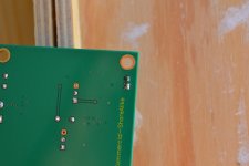
Phil: so here is the promised photo of the spdif connectors - hope this is what you wanted to see ;-) I ordered a new bnc cable, maybe the old one is the culprit. If changing the cable doesn't make a difference I will reposition the bnc connector so it is as close as possible to the spdif input port. just want to try the new cable first because I will have to make the whole front new for moving the bnc port - it needs a much bigger hole than the audio connectors so I can't just swap them ;-)
Gorgomat: thanks for the explanation. I do use a shielded cable for the connection from PC to DAC. I didn't think the "short" wire in the dac could cause a problem *g* Would this wire work? ML 238-5: Mikrofonleitung, 2x0,38mm, flach, 5m-Ring bei reichelt elektronik
It feels like I should have asked some more questions. Well, now I pay my apprentice's due in shipping costs ;-)
Attachments
Last edited:
Phil: good idea with continuity check. Dont know why i didnt think of that by myself. looks like there is a loose connection in the wire i have. will wait for the new wire and try again
Gorgomat: good. If i replace the wire with the shielded cable the length of it shouldnt be such an issue any more, right?
Gorgomat: good. If i replace the wire with the shielded cable the length of it shouldnt be such an issue any more, right?
If you have a long spidf wire Inside the cabinet like your photograph shows .Try to keep the same impedance between the spidf wire between the cabinet plug and pcb plug with the one you use between the cabinet and your streamer/reader/computer audio card !
75 ohms is better than 50 ohms for spidf, even if you stay with non matched impedance plug like RCAs are.
Of course if your plugs are 75 ohms BNC from the computer to the cabinet spidf plug : even better than RCAs !
75 ohms is better than 50 ohms for spidf, even if you stay with non matched impedance plug like RCAs are.
Of course if your plugs are 75 ohms BNC from the computer to the cabinet spidf plug : even better than RCAs !
The w8804 layout of the Subbu V3 is very sensible: you can hear all the change made around it.
I firstly begann with rca like you did but with shorter wire than yours . With the advices of J-P, Garry and Korben69 I swaped with RG59 75 ohms wire + BNC with a hearable greater result (better bass, wider top & low end). After I putted a BNC pcb plug to go even shorter. some photographs on the Modyfing thread if you have the courage to surf !
Coax is not so good for analog output stage and what you did here is enough with the same rule : the shorter the better ! But the coax is the way to go for RF signals like the spidf one (slow RF... but at least RF !)
I firstly begann with rca like you did but with shorter wire than yours . With the advices of J-P, Garry and Korben69 I swaped with RG59 75 ohms wire + BNC with a hearable greater result (better bass, wider top & low end). After I putted a BNC pcb plug to go even shorter
. some photographs on the Modyfing thread if you have the courage to surf !Coax is not so good for analog output stage and what you did here is enough with the same rule : the shorter the better ! But the coax is the way to go for RF signals like the spidf one (slow RF... but at least RF !)
gorgomat: then rg59 it is
eldam: checked out the thread but found only 2 pics from you, where you couldn't see much ;-) anyway, lots to be learned for me. I think i will redo the housing - this time with better layout *grins* I start wondering if a metal box would be better - em interference wise?
eldam: checked out the thread but found only 2 pics from you, where you couldn't see much ;-) anyway, lots to be learned for me. I think i will redo the housing - this time with better layout *grins* I start wondering if a metal box would be better - em interference wise?
You could see a photograph with the BNC plug for PCB somewhere (maybe not a macro photograph : you must solder it from the bottom of the pcbto respect the layout of the plug (solid leads).
For the cabinet : aluminium is better or there is the advice from Pedja Rogic given to some AYA 2 builders : wood + copper inside for EMC is even better than simple aluminium casing ! (and to work I'm not sure too thin aluminium is enough (1 or 2 mm economical box is maybe not enough !)
For the cabinet : aluminium is better or there is the advice from Pedja Rogic given to some AYA 2 builders : wood + copper inside for EMC is even better than simple aluminium casing ! (and to work I'm not sure too thin aluminium is enough (1 or 2 mm economical box is maybe not enough !)
This is my case for my DAC ( though it is a different board than discussed in this topic ).
Selfmade out of spare Aluminum and other junk I had laying around, also grounded. Only the Board itself has no connection to the ground itself but the case is shielded
http://www.diyaudio.com/forums/digital-line-level/166807-dac-gallery-20.html#post4228591
Selfmade out of spare Aluminum and other junk I had laying around, also grounded. Only the Board itself has no connection to the ground itself but the case is shielded
http://www.diyaudio.com/forums/digital-line-level/166807-dac-gallery-20.html#post4228591
Phil: good idea with continuity check. Dont know why i didnt think of that by myself. looks like there is a loose connection in the wire i have. will wait for the new wire....
Please focus in the SPDIF wire, even if a coax one is better, check the link first.
When done, we'll explore W7 Audio configuration
Step by step debug.
I could be online tomorrow afternoon, Gmail chat.
Let me know
Regards,
Phil
thanks to all of you for all the helpful replies
phil: are you talking about the wire from spdif out of the board to bnc plug? did a continuity check there after soldering and everything was good. since my old bnc to bnc wire is faulty i have to wait for a new one for further checks i think? I mean i could simple use a copper wire to bridge bnc out from computer to bnc/spdif in from dac, but i don't know what kind of new problems that would cause... *lol* If its easier for you to troubleshoot via chat/skype or whatever I am happy to do that.
gorgomat: nice case will do a new case after i sorted out the other stuff *g*
phil: are you talking about the wire from spdif out of the board to bnc plug? did a continuity check there after soldering and everything was good. since my old bnc to bnc wire is faulty i have to wait for a new one for further checks i think? I mean i could simple use a copper wire to bridge bnc out from computer to bnc/spdif in from dac, but i don't know what kind of new problems that would cause... *lol* If its easier for you to troubleshoot via chat/skype or whatever I am happy to do that.
gorgomat: nice case
will do a new case after i sorted out the other stuff *g*
Last edited:
thanks to all of you for all the helpful replies
phil: are you talking about the wire from spdif out of the board to bnc plug? did a continuity check there after soldering and everything was good.
Ok, check it again, and if it reveals OK then the trouble in elsewhere.
BTW I'll suggest to dig into W7 Audio configuration.
Default is, depending on your onboard audio card, usually 24/48...
Let see tomorrow, time to have some rest
Regards,
Phil
- Home
- Source & Line
- Digital Line Level
- Build thread - building the Subbu DAC V3 SE