interesting that something seems to be loading Q1 down without the dac and then its the only one not loaded down, or rather showing error, with the dac attached. there arent that many places that could cause an error across both channels; a consistent one at that.
i'm thinking heatsink or something is shorting across Q2-4 somehow. its one of the only places that is possible to have connectivity across both channels and its the most common thing that causes problems with this build.
do you get connectivity from V+ on the right side, to V+ on the left side?
i'm thinking heatsink or something is shorting across Q2-4 somehow. its one of the only places that is possible to have connectivity across both channels and its the most common thing that causes problems with this build.
do you get connectivity from V+ on the right side, to V+ on the left side?
Last edited:
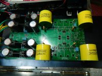
not ground, the rails. what about those holes youve drilled out in the PCB/copper? they could then cause a short through the brass standoffs. or is that an illusion? it looks like youve drilled them out for easier access. normally those holes do not have connection to the surrounding copper and you have most certainly made sure they do now if youve drilled them out, looks like R25/26 may be close to touching too. if it is what it looks like, that was a pretty radical and perhaps destructive move.
no worries glad to help
no worries glad to help
Last edited:
Are in trouble: (
....Zener are removed.
Any advice please!
What is the reason for this change?
What is the reason for this change?
Somewhere in the thread it was said that because of wrong mounted zener voltage can be 0.8V to (S) ...
not ground, the rails. what about those holes youve drilled out in the PCB/copper? they could then cause a short through the brass standoffs. or is that an illusion? it looks like youve drilled them out for easier access. normally those holes do not have connection to the surrounding copper and you have most certainly made sure they do now if youve drilled them out, looks like R25/26 may be close to touching too. if it is what it looks like, that was a pretty radical and perhaps destructive move.
no worries glad to help
We checked several times.
When Buffalo is offline I have the following:
- There is no contact between the Drain and Heatsink;
- There is no contact between GND and Heatsink;
- There is no contact between the left and right GND;
- R25/R26 area no contact between channels;
- All screws no contact with PCB and with GND;
- Supports copper have no contact with GND;
- Voltages are 1.65V(Source) - 21 .. 23 V (Drain) Q1-Q4;.
- Heatsink heats up to 50 degrees over 30 minutes.
When put Buffalo:
- I GND connection between the left and right channel ( ?? );
- Supports copper have no contact with GND;
- The Q1 we 1.65V (S) - 21.8V (D)
- The Q2-Q3-Q4 we 0.8V(S)- 45V (D)


For some time we worked on Edel Renderer - Ian's FIFO Buffalo DAC - OPC NTD1 I / V. Now everything works perfectly and I am very pleased with the sound. I am impressed by DNT1 - is something ... big! It's different from Legato. I always returned to NTD1.
A dynamic and extraordinary presence, the bass is fabulous!!!
I am very much to thank OPC for NTD1
And thanks for all the support's Qusp
Excuse my English: (
A dynamic and extraordinary presence, the bass is fabulous!!!
I am very much to thank OPC for NTD1
And thanks for all the support's Qusp
Excuse my English: (
Attachments
Hi
Before I get on with building a differential amplifier, I need to do the balanced to single ended conversion from OPC D1 to my SE tube amplifier. I have decided to go for a transformer solution. I have looked at sowter 3575 3575 will this one do the job for me?
I am wondering how to connect the transformer - did I get it correct in attached picture or am I completely lost here? Do I attach the transformer shield to ground on OPC D1 or ground on tube amplifier. What about the center tap (blue 5)
I used the excel sheet provided earlier by qusp to calculate output cap size to around 1,5uF-2uF (input impedance 50Kohm on tube amp). But I am wondering if this holds true, when using the transformer.
I feel a little lost here any advice really be appreciated
Thanks
Rolle
Before I get on with building a differential amplifier, I need to do the balanced to single ended conversion from OPC D1 to my SE tube amplifier. I have decided to go for a transformer solution. I have looked at sowter 3575 3575 will this one do the job for me?
I am wondering how to connect the transformer - did I get it correct in attached picture or am I completely lost here? Do I attach the transformer shield to ground on OPC D1 or ground on tube amplifier. What about the center tap (blue 5)
I used the excel sheet provided earlier by qusp to calculate output cap size to around 1,5uF-2uF (input impedance 50Kohm on tube amp). But I am wondering if this holds true, when using the transformer.
I feel a little lost here
any advice really be appreciatedThanks
Rolle

Hi Rolle,
That transformer looks pretty decent, and distortion isn't too bad either.
If you set up the NTD1 circuit carefully, and match the voltage and the drains of each fet, then you can get away with no caps at all providing the transformer has some tolerance of small DC offsets.
Worst case, all you need is one cap to block DC in the transformer winding across both drains. The value of the cap needs to be sufficient to not cause an LF rolloff with the reflected impedance from the input of the tube amp.
I liked the idea of using a center tapped transformer primary, and putting the cap between the two windings, but it really doesn't matter where it goes.
If I were you, I'd put the transformer in the DAC case rather than in the amp case as your diagram implies, and just use them to add SE outputs to the DAC.
Cheers,
Owen
Hi Owen
Thanks alot for taking the time to answer my question reg. BAL-SE transformer connection I have ordered the transformers from sowter this evening and can't wait to get them connected
good idea to put the transformers in the dac case - will do that
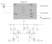
I have attached new picture just to be absolutely sure I have understood you comments correctly. So basically I can short the output coupling cap (C52) and get away with a coupling cap in position C29 to block DC across the transformer windings (4 & 6) to be on the safe side - right?
regarding calculating the capacitor size - I just realise that R20 (100k) is parallel with input impedance of my tube amp 50k - so this gives me R=33k to use in formula for corner freq F = 1/(2 * pi * C * R) right?
Thanks
Thanks alot for taking the time to answer my question reg. BAL-SE transformer connection
I have ordered the transformers from sowter this evening and can't wait to get them connectedgood idea to put the transformers in the dac case - will do that
I have attached new picture just to be absolutely sure I have understood you comments correctly. So basically I can short the output coupling cap (C52) and get away with a coupling cap in position C29 to block DC across the transformer windings (4 & 6) to be on the safe side - right?
regarding calculating the capacitor size - I just realise that R20 (100k) is parallel with input impedance of my tube amp 50k - so this gives me R=33k to use in formula for corner freq F = 1/(2 * pi * C * R) right?
Thanks
Attachments
Hi Rolle,
What you have listed is exactly correct, and your diagram is also correct. If I were you I would be very tempted to try and make it work with no coupling caps at all, but the safest method would certainly be to keep just one of them.
Both R20 and R23 are no longer required for your application, so you should remove them. They were intended to keep DC on the output side of the coupling caps to a minimum, but that won't be an issue for you as you have a transformer.
That also means that you only need to size the caps for the reflected input impedance of the tube amp you're driving. If I were you though, I would go for the largest value film cap you can fit/afford, and bypass it with smaller value film caps.
Cheers,
Owen
Hi
just want to share my experience
I got the Sowter 3575 transformers and hooked them up the other day. I bought 2 Jantzen superior Z-cap 3,3uF and bypassed them with mundorf silver/oil 0,22uF (I am not really sure I dare going down the cap-less road )
But WOW - what a big difference in sound - now I hear the highend sparkle I was missing and much better seperation of instruments . I get a Fullbodied warm sound but still with good highend detail - instuments sounds correct like when you are at a live concert - nice balance from top to bottom. Female and male voices sounds wonderfull. Music just flows effortless.
Thanks Owen for all your efforts in making this I/V possible and the help an guidance you and others in this thread have given. This is truelly an amazing I/V and for sure my new reference I/V
Have a nice day
Rolle
just want to share my experience
I got the Sowter 3575 transformers and hooked them up the other day. I bought 2 Jantzen superior Z-cap 3,3uF and bypassed them with mundorf silver/oil 0,22uF (I am not really sure I dare going down the cap-less road
) But WOW - what a big difference in sound - now I hear the highend sparkle I was missing and much better seperation of instruments . I get a Fullbodied warm sound but still with good highend detail - instuments sounds correct like when you are at a live concert - nice balance from top to bottom. Female and male voices sounds wonderfull. Music just flows effortless.
Thanks Owen for all your efforts in making this I/V possible and the help an guidance you and others in this thread have given. This is truelly an amazing I/V and for sure my new reference I/V
Have a nice day
Rolle
- Home
- Source & Line
- Digital Line Level
- Build Thread - A New Take on the Classic Pass Labs D1 with an ESS Dac