Not really to "protect" the opamp, but to prevent it from oscillations. It provides some isolation for the capacitance that the output cable may have have.yeah but you can omit the one on the IVY I would think, well I did too with the one I tried for the portable. I assume its to protect the opamps from the capacitive load and also perhaps output short protection yes? probably says in the manual.....
obviously the capacitive load isnt going to KILL the IV opamps, protect was just a choice of words. 'protect' like 'buffer from' the capacitive load.
yeah i'm doing the same thing too. but for my IV stage/headamp too depending on the quote I get i'd like to go silver immersion PTFE on 4oz Cu, also relegating all shutdown signals to remote MCU and relay based switches, so I can keep the length of wire from the battery to the dac/amp as short as possible. all cells have had the tabs removed and hardwired together with 2 x 18AWG duelund silver foil (low Z and low profile), a braided 3x24AWG UPOCC silver wire connection for +/- and a 16AWG silver foil center tap.
the whole thing including the IV, amp, volumite, dac and buffered transformer coupled spdif line driver all exists in an area of ~ 4" x 3". at the moment the regulator board and molex interface is on a board 1.5x2", but I plan to make a PCB only slightly smaller than the area that contains the relay, regs and battery/shutdown manager and LED driver with nice thick traces for the direct battery connections and a heavy duty ground plane for as much of the underside as possible. then try to arrange everything so that DIY 18AWG silver pinheaders connect and hold everything together. the case is 7 x 4 x 1.1" and mostly the battery pack.
craziest wiring job i've ever done on a power supply, but as you say, keeping the length and impedance of the connection as low as possible, is about all there is left to do to these things to improve performance, since the output Z is better than most lowZ caps already. I have however tripled up on the input/reservoir caps for the IV which are low Z SMD oscons anyway. this is all wire I had lying around anyway and the lengths are short, all the same its the most uber looking battery pack i've ever seen
so yeah I was going to map out the scale drawing as well, for making the 'harness' so a layout drawing would be very handy
stephen1212 said:t seems to me that the only hope of improving the power supplies is to eliminate as much wire as possible. I am thinking of a board that would stack above or between the dac and the I/V board. Is there a 1 to 1 drawing with the mounting and power hole positions and sizes available?
yeah i'm doing the same thing too. but for my IV stage/headamp too depending on the quote I get i'd like to go silver immersion PTFE on 4oz Cu, also relegating all shutdown signals to remote MCU and relay based switches, so I can keep the length of wire from the battery to the dac/amp as short as possible. all cells have had the tabs removed and hardwired together with 2 x 18AWG duelund silver foil (low Z and low profile), a braided 3x24AWG UPOCC silver wire connection for +/- and a 16AWG silver foil center tap.
the whole thing including the IV, amp, volumite, dac and buffered transformer coupled spdif line driver all exists in an area of ~ 4" x 3". at the moment the regulator board and molex interface is on a board 1.5x2", but I plan to make a PCB only slightly smaller than the area that contains the relay, regs and battery/shutdown manager and LED driver with nice thick traces for the direct battery connections and a heavy duty ground plane for as much of the underside as possible. then try to arrange everything so that DIY 18AWG silver pinheaders connect and hold everything together. the case is 7 x 4 x 1.1" and mostly the battery pack.
craziest wiring job i've ever done on a power supply, but as you say, keeping the length and impedance of the connection as low as possible, is about all there is left to do to these things to improve performance, since the output Z is better than most lowZ caps already. I have however tripled up on the input/reservoir caps for the IV which are low Z SMD oscons anyway. this is all wire I had lying around anyway and the lengths are short, all the same its the most uber looking battery pack i've ever seen
so yeah I was going to map out the scale drawing as well, for making the 'harness' so a layout drawing would be very handy
Who manufactures silver immersion PTFE on 4oz Cu boards ? Any pictures yet? For audio out I am considering two ( LME49990 - LME49600 ) balanced to single ended to replace the balse on the IVY and feed the balanced outputs then into another to provide single ended output. Obviously dual mono with two B2 DACs.
will put up some pics later in the week. its in pieces again at the moment on the bench. most high quality PCB manufacturers will do Rogers PTFE/glass substrate with silver immersion over Cu; not sure that everyone does 4oz but some will.
I would love to get it done at Tresimine here in Sydney to keep it in the country, but depends on the quote they come back with when i'm finished this round of testing and get the final design done. so yeah just google Rogers PTFE substrate PCB manufacture in your location
some devices I cant try yet until I get the PCBs done, as they arent solderable by hand. like the new DFN package linear tech MCU/battery charge monitor and start/shutdown manager. the amp is DC coupled, so gotta make sure that low charge is handled properly to protect my JH13's. at the moment i'm just using a perf mockup with LT1763 on one of Peranders soic8->Dip PCBs without the dip part just wired down onto some perf and working on LT1964 (negative compliment of 1763) today for the latest tests and I havent been using it portable for a bit until I finish with the mounting hardware, then finally i'll get some front and rear panels milled for the hammond case, for now i'm using the stock panel, but the hole for the DSUB on the rear is a bit rough because I lost my patience with the file and got the dremel out .
.
I need to change the termination resistors and transformer (murata) on the spdif input too, as I just changed from 75R BNC to lemo 50 ohms mini BNC and may change to the DFN 1763, because its got all the functionality, where the soic8 package adjustable variant you have to choose either having the bypass pin or shutdown pin, I chose the bypass pin version, which allows you to bypass the internal reference, lowering noise and improving transient response. I would like the shutdown pin as well though, to allow the whole thing to be switched off by the charge monitor as is, without the need for an external relay/latch. i'm probably over thinking/over designing all of this, but its a fun exercise. I just cant face the thought of my JH13 dying a painful death from DC while deep in my ear canal if I fall asleep with them in or whatever.
perhaps Russ or someone could shed some light on what happens with the OPA1632 when power is low, or cut? I really want to keep this thing DC coupled, of course the easy option would be to put some caps on the output. or a servo, but finding a fast enough and accurate enough servo is another thing, I dont have the facility to zero VCOM on this IV/amp board, but I think it will be fine anyway, I do wonder about what happens at the limits of operation though, so I want avoid going there, I dont have a scope.
i've derailed the thread enough for one day though, sorry about the verbal dribble guys, perhaps I should start a thread
I would love to get it done at Tresimine here in Sydney to keep it in the country, but depends on the quote they come back with when i'm finished this round of testing and get the final design done. so yeah just google Rogers PTFE substrate PCB manufacture in your location
some devices I cant try yet until I get the PCBs done, as they arent solderable by hand. like the new DFN package linear tech MCU/battery charge monitor and start/shutdown manager. the amp is DC coupled, so gotta make sure that low charge is handled properly to protect my JH13's. at the moment i'm just using a perf mockup with LT1763 on one of Peranders soic8->Dip PCBs without the dip part just wired down onto some perf and working on LT1964 (negative compliment of 1763) today for the latest tests and I havent been using it portable for a bit until I finish with the mounting hardware, then finally i'll get some front and rear panels milled for the hammond case, for now i'm using the stock panel, but the hole for the DSUB on the rear is a bit rough because I lost my patience with the file and got the dremel out
. I need to change the termination resistors and transformer (murata) on the spdif input too, as I just changed from 75R BNC to lemo 50 ohms mini BNC and may change to the DFN 1763, because its got all the functionality, where the soic8 package adjustable variant you have to choose either having the bypass pin or shutdown pin, I chose the bypass pin version, which allows you to bypass the internal reference, lowering noise and improving transient response. I would like the shutdown pin as well though, to allow the whole thing to be switched off by the charge monitor as is, without the need for an external relay/latch. i'm probably over thinking/over designing all of this, but its a fun exercise. I just cant face the thought of my JH13 dying a painful death from DC while deep in my ear canal if I fall asleep with them in or whatever.
perhaps Russ or someone could shed some light on what happens with the OPA1632 when power is low, or cut? I really want to keep this thing DC coupled, of course the easy option would be to put some caps on the output. or a servo, but finding a fast enough and accurate enough servo is another thing, I dont have the facility to zero VCOM on this IV/amp board, but I think it will be fine anyway, I do wonder about what happens at the limits of operation though, so I want avoid going there, I dont have a scope.
i've derailed the thread enough for one day though, sorry about the verbal dribble guys, perhaps I should start a thread
Last edited:
SPDIF input experts???s
I am expecting my B-II module to arrive quite soon, and have everything ready to drop it with the Legato, power supplies, etc. I am now wondering about getting the SPDIF input right: I have a 75 ohm bnc jack on the chassis, and only about 2 cm of wiring to get from the jack (yes solder cup...) to the board. I assume on the board there is 75R termination. Considering the short distance, am I going to be inviting any problems by just running 2 cm. 24 gauge wire to the board, and not bothering with trying to strip and terminate such a short run of 75 coax?
Additionally, would I expect to gain anything by adding an pulse transforrmer (I have a Lundahl 1572 I could use)? Any sources I expect to use will have transformer coupled SPDIF outputs.
Thanks in advance for help...
With this level of technology and herculean efforts, I am surprised you are not going directly to I2S...
Anand.
Nyc
Yes, ultimately I do plan to go I2S-but only when I find a suitable I2S source. Hopefully TPA's XMOS USB solution will be "all that" when it is available, but I know that developing something like this might take awhile to get bug free and performing optimally.
In the meantime I plan on evaluating the B-II via SPDIF, and comparing with other SPDIF DACs as well as my bel canto CD-1.
For I2S I want to be able to install a board with uncompromised performance, which allows short I2S lines, and handles sample rates up 24/192-right now this does not exist, at least not that I am aware of. I would also prefer a USB-I2S solution that requires no additional drivers, but at this point such a solution seems unlikely...
Last edited:
I am expecting my B-II module to arrive quite soon, and have everything ready to drop it with the Legato, power supplies, etc. I am now wondering about getting the SPDIF input right: I have a 75 ohm bnc jack on the chassis, and only about 2 cm of wiring to get from the jack (yes solder cup...) to the board. I assume on the board there is 75R termination. Considering the short distance, am I going to be inviting any problems by just running 2 cm. 24 gauge wire to the board, and not bothering with trying to strip and terminate such a short run of 75 coax?
Additionally, would I expect to gain anything by adding an pulse transforrmer (I have a Lundahl 1572 I could use)? Any sources I expect to use will have transformer coupled SPDIF outputs.
Thanks in advance for help...
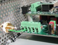
I did it short wired.
Attachments
off topic but it's been quiet...
I think this quote is very wise.
Something happened yesterday that reminded me of this comment. I merely replaced the motherboard, CPU and memory in my PC sound server. Nothing more. The difference in sound was surprising (and better, thankfully)! The old motherboard was more than adequate for the task computationally. The new one [Gigabyte 880 series] has extra copper in the ground and power planes in order to act as a heat sink for passive chip cooling. Whatever the source for the sonic improvement, "jitter" would seem to be the most likely variable. Upsampling using Quicktime (w/ ASIO output to an external sound board from which I2S is hijacked), the improvements are lost when I push frequency up to 192kHz. 96kHz is preferred - slightly better than 88, which is better than 44, which is about equal to 192. Surprising that the computer source could make all of the Twisted Pear gear so much better! Obviously, our individual experiences with jitter will vary, but I don't assume that any component is immune to it's effects. I just wish that finding and eliminating it wasn't such voodoo...
My experience with other ASRC solutions (like the TI 4192) has shown that although ASRC does reduce measured jitter, the DAC still sounds better every time one reduces the jitter level at the input to the ASRC. Some digital engineers have tried to explain why this is, saying that the ASRC reduces (actually they say "filters") the incoming jitter, but really just chages the jitter to other artifacts that demodulate to noise in the output of the DAC. I do not fully understand the process, but my listening experience suggests that it is always wise to feed a DAC (reclocking or not) the lowest jitter data stream possible, and that DAC claims like: "immune to jitter" are generally not true.
I think this quote is very wise.
Something happened yesterday that reminded me of this comment. I merely replaced the motherboard, CPU and memory in my PC sound server. Nothing more. The difference in sound was surprising (and better, thankfully)!
The old motherboard was more than adequate for the task computationally. The new one [Gigabyte 880 series] has extra copper in the ground and power planes in order to act as a heat sink for passive chip cooling. Whatever the source for the sonic improvement, "jitter" would seem to be the most likely variable. Upsampling using Quicktime (w/ ASIO output to an external sound board from which I2S is hijacked), the improvements are lost when I push frequency up to 192kHz. 96kHz is preferred - slightly better than 88, which is better than 44, which is about equal to 192. Surprising that the computer source could make all of the Twisted Pear gear so much better! Obviously, our individual experiences with jitter will vary, but I don't assume that any component is immune to it's effects. I just wish that finding and eliminating it wasn't such voodoo... What we need is a transport protocol inmune to jitter. You have them all around you in almost any cheap device.
Sorry for being tiring but, I cannot stop wondering why all other areas like telecommunications had surpassed the jitter issue, and in the 21th century, we are still suffering corrupted digital transfers..
Really, I cannot get it inside my head. USB transfer to a pendrive, compact disk storage, ethernet connections, SATA links, even WI-FI! They're all inmune to jitter, have buffers and recovery mechanisms.
Let's say, it would be solved by implementing an easy point-to-point protocol based on packets. CRC error detection and such. Even the good old Ethernet will work, we don't need low latency or high bandwidth (Meaning bytes per second, not audio frecuency response). Even 1.000ms of latency will work, whatever it takes. Even 687.5 Kb/s (44,000 x 16 / 1024) data rate would be enough for CD quality. That's a DSL link of 5.5Mbits, so this theoretical protocol could deliver CD quality jitter-free to any part of the world by just having a "cheap" internet connection.
Just buffering the incoming packets in a memory, and then processing it as it needs the data. This would work prefect for applications not demanding low latency, like listening to music.
We need a whole new philosophical approach. Would it be acceptable for you if some of these characters you are reading now would be randomly changed for another ones? "it's because of jitter, you've to live with it"
NO! NEVER! totally unacceptable in any consumer enviroment, even less in a business one. So why accept and approve that as normal in the Audio enviroment?
Had the world gone mad or is just me thinking too much?
Is there any other tech guy out there to share impressions?
In essence you're asking for a buffer inside the DAC chips, and you prefer an ethernet interface to the current I2S interface. That makes sense, but the DAC manufacturers aren't there yet. Give them a few years of further integration and we might get there.
And CD Quality is 44000 x 2 / 1024 in Kb/s, as it's 44Khz and 16 bits (i.e. 2 bytes).
And CD Quality is 44000 x 2 / 1024 in Kb/s, as it's 44Khz and 16 bits (i.e. 2 bytes).
In essence you're asking for a buffer inside the DAC chips...
Or perhaps a separate chip on the same board. The important initiative would be to introduce some kind of error-checking. One persistent issue relative to the chip market will be acceptable response latency in the face of very diverse applications for which DACs are required. (e.g. video synch, live performance, etc.)
Error checking is useless without a buffer. If you detect an error but there's no time to perform a re-transmit of the data the error could just as well go on undetected. So you need a buffer to obtain data to decode right now, and that buffer has to be filled fast enough to not run out of data. But if that buffer is outside of your DAC chip, you have to get the data into the DAC eventually, and then you're running into the same problems designers had before.
Examples of playing DSD sources on Buffalo II
These days, I find three examples of playing DSD sources using Buffalo II DAC in Japanese blog sites. I'd like to introduce them on this post.
There are two major sources.
1. Tapping DSD signals from commercial SACD players
2. "USB Audio board" kit + "PlayAudio" software by ElectrArt
1. Buffalo II with SACD players
A. "Ken" reported that he connected his SONY SCD-XE6 to Buffalo II in his blog page.
SACD‚ÌŠO•t‚¯DAC ƒPƒ“‚̃I�[ƒfƒBƒIƒ�ƒ‚/ƒEƒFƒuƒŠƒuƒ�ƒO (In Japanese)
His impression was "staging is deep and more natural".
B. Sunacchi's case, his player is SONY SCD-X501
SDƒJ�[ƒhƒvƒŒƒCƒ„�[“ó�†‹@�i‚»‚Ì‚R�j: Ama Ama Audio Visual(In Japanese)
He got the similar impression with Ken's. "Sound is more stereoscopic and natural."
2. Buffalo II with ElectrArt's USB Audio board
The "USB Audio board" is designed and distributed to audiophiles by ElectrArt.
ElectrArt?Digital Audio??? ???????? USB AUDIO???13(In Japanese)
Using the board with his proprietary software "PlayAudio",
ElectrArt?Digital Audio??? ???????? PlayAudio ?????????2(In Japanese)
we can record and play DSD64 and DSD128 as well as PCM 44.1 - 192 kHz by way of USB.
"Hiyohiyo" reported his successful play of both DSD64 and DSD128 files available on 2L commercial site with the USB Audio board connected to Buffalo II.
?????: 2L?DSD64????DSD128???(In Japanese)
Are there any other DSD sources?
Last edited:
You forgot to multiply it times 16 bits.And CD Quality is 44000 x 2 / 1024 in Kb/s
You are right Brian, my fault.
No, I didn't. To get a datarate in bytes, one has to divide the bitrate by 8. So a 16 bit wide signal takes 2 bytes. Multiply this by your sample frequency (44000 samples/sec) and you get bytes/s. Divide it by 1024 and you get Kb/s.You forgot to multiply it times 16 bits.
- Status
- This old topic is closed. If you want to reopen this topic, contact a moderator using the "Report Post" button.
- Home
- More Vendors...
- Twisted Pear
- Buffalo II