Being new to DIY i would certainly suggest the KISS rule
Just go a single stereo buffalo, this will be much easier to build and perform better when driving headphones anyway.
Buff-II with placid PSU
IVY3 with placid BP PSU
(9+9) toroidal
(15+15) toroidal
If you're only going to use 1 SPDIF input, well the buffalo itself accepts SPDIF so you won't need a receiver. If you want multiple inputs get the MUX.
You won't need an extra power supply for that, you can run it for the buffalo's supply.
interested in your conclusion of a single unit driving HP being superior. not arguing with it; rather intrigued.
@ Russ or Brian: as you know i'm playing with various battery powered scenarios with the buffalo II in a portable unit. i'm using LiFePo4 batteries. about to try it out without any regs at all apart from the onboard units on the dac board. I have been using a 6 cell ~20vdc LiFePo4 pack, but for this instance i'm just using a center tapped pack with 4 larger 2200mah cells. with a full charge that amounts to +/-6.8v max and quickly drops to 6v6, where it pretty much stays till empty, dropping to 6v4 over the entire usable life (7-8hrs) then dropping quickly; but i'm using logic to cut off at +/- 6v2vdc. is the dac board equipped to deal with this voltage drop directly? ie will the LT1763 regs cope with an input/output voltage of ~5v? I mean you specify the supply voltage at 5v5, will the extra 1vdc be a problem? ould be great to have the only IC's in the signal path be the onboard regs, rather than an extra LT1763 to drop the supply to 5v5. the IV/headamp i'm using copes with the larger 6 cell pack directly just fine, so the lower voltage will be a walk in the park, but wanted to make sure the dac board will cope.
thanks
The 5.5V recommendation has nothing to do with the LT1763s. Those will be ok up to say 6.5V(maybe 7V though I have not tried it lately). It is all about the AVCC module. The AVCC module absolutely should not be used above 5.5V. It will eventually kill it's controlling opamp.
Bottom line is. Your on your own on this one buddy.") Read the datasheets and make an informed decision.
Read the datasheets and make an informed decision.
Bottom line is. Your on your own on this one buddy.
Read the datasheets and make an informed decision.re direct Headphone drive w/IVY
A big question is what headphone? Look up Ohms and sensitivity – you really want an idea of these basics to recommend a amp circuit
I certainly wouldn't hang my K701 or any orthodynamic headphone from the OPA1632 output and claim the audiophile journey was over
This is wrong by the datasheet numbers:
the datasheet actually shows higher Z headphones (the best case) could be driven to something over 300 mWrms – nowhere near “2W”
lower Z 32 Ohm headphones would only be driven to ~50mWrms
looks like Twisted Pear misread the OPA1632 datasheet, the IVY manual gets the op amp spec wrong
150 mA is not the op amp's current drive ability - it is a value beyond which the chip may be damaged
for usable output current a better place to look is the min short circuit current spec: +50/-60 mA - and that # is for no output V
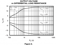
then look at the output V vs load R plot (fig 9) to see that ~50-60 mA also seems to be the working current limit of the (hopefully "typical") device the plot was made with
gain resistors should be changed to get Vswing to match the headphone drive requirements but the fig 9 graph's ~50-60 mA peak current is going to be a limit - and the DAC IV feedback R current is also part of the output current budget
the 22 Ohm R isolate the op amp output from cable Cload which can cause instability - reducing to 5-10 Ohms or replacing with properly (over) sized ferrite bead core inductors would be my recommendation for direct headphone output because headphone cables have capacitance too
A big question is what headphone? Look up Ohms and sensitivity – you really want an idea of these basics to recommend a amp circuit
I certainly wouldn't hang my K701 or any orthodynamic headphone from the OPA1632 output and claim the audiophile journey was over
This is wrong by the datasheet numbers:
With 15V rails, the OPA1632 can deliver upwards of 2W.
the datasheet actually shows higher Z headphones (the best case) could be driven to something over 300 mWrms – nowhere near “2W”
lower Z 32 Ohm headphones would only be driven to ~50mWrms
looks like Twisted Pear misread the OPA1632 datasheet, the IVY manual gets the op amp spec wrong
150 mA is not the op amp's current drive ability - it is a value beyond which the chip may be damaged
for usable output current a better place to look is the min short circuit current spec: +50/-60 mA - and that # is for no output V
then look at the output V vs load R plot (fig 9) to see that ~50-60 mA also seems to be the working current limit of the (hopefully "typical") device the plot was made with
gain resistors should be changed to get Vswing to match the headphone drive requirements but the fig 9 graph's ~50-60 mA peak current is going to be a limit - and the DAC IV feedback R current is also part of the output current budget
the 22 Ohm R isolate the op amp output from cable Cload which can cause instability - reducing to 5-10 Ohms or replacing with properly (over) sized ferrite bead core inductors would be my recommendation for direct headphone output because headphone cables have capacitance too
Last edited:
ahh OK, hehe fairy'nuff mate . I was actually planning on trying doing away with the AVCC module in the same run of tests anyway, feeding the AVCC and VOSC 3v3 direct from one of the battery connections, which would net me slightly increased runtime as a nice byproduct of doing away with the shunted and dropped energy. yeah I read the 1763 sheets as i've been playing around with them, fantasic range of regs that family, also playing with the LT3032 bipolar LDO for my IV with the higher voltage pack setup; i'm using a 1763 at the moment to drop the voltage to 5v5 from the higher voltage 6 cell pack. it seemed to me they would be OK, but I guess i'll look into the devices on the shunt.
the dac will cope quite well with higher AVCC voltages than 3v3 anyway according to dustin (obviously i'm not going to feed it 6v8 though ) so I guess will see how I go
. I was actually planning on trying doing away with the AVCC module in the same run of tests anyway, feeding the AVCC and VOSC 3v3 direct from one of the battery connections, which would net me slightly increased runtime as a nice byproduct of doing away with the shunted and dropped energy. yeah I read the 1763 sheets as i've been playing around with them, fantasic range of regs that family, also playing with the LT3032 bipolar LDO for my IV with the higher voltage pack setup; i'm using a 1763 at the moment to drop the voltage to 5v5 from the higher voltage 6 cell pack. it seemed to me they would be OK, but I guess i'll look into the devices on the shunt. the dac will cope quite well with higher AVCC voltages than 3v3 anyway according to dustin (obviously i'm not going to feed it 6v8 though
) so I guess will see how I go
Last edited:
This is wrong by the datasheet numbers:
Quote:
Originally Posted by BrianDonegan
With 15V rails, the OPA1632 can deliver upwards of 2W.
I claim "beer posting"
 on that one...
I was actually planning on trying doing away with the AVCC module in the same run of tests anyway, feeding the AVCC and VOSC 3v3 direct from one of the battery connections
Done that, well worth it. LiFePO4 batteries rock. Use them for the clock too.
Done that, well worth it. LiFePO4 batteries rock. Use them for the clock too.
+1 ditto.
LiFePO4's directly feeding the Sabre are amazing.
Haven't tried the clock yet. Had to box up my system for a move to a new crib.
for usable output current a better place to look is the min short circuit current spec: +50/-60 mA - and that # is for no output V
I must interject here. Because while I appreciate the good intent of the poster there are a few factual problems.
I have actually tested the chip.
First, the output short cct figure of 60-85ma with is each output to a virtual GND (mid rail). This is indeed just as the datasheet describes. This is because of the open loop output impedance. I at first was scratching my head over this until I actually tested the chip.
Now if you bridge tie the load (which figure 9 does, but does not go far enough) you can quite easily get 150ma out of the OP1632, as long as its an AC signal. Of you try that at DC or close you will quickly over heat the chip unless you use some incredible heat sinking.
Remember 150ma into a 32 ohm load only requires a differential voltage of 4.8V True enough that's only about .75W but thats still a lot of power for a headphone.
Also remember that the max rail voltage for the opa1632 is 16.5VDC not 15V.
Revise the chart accordingly.It is true that the feedback resistors will eat up some of the current, but not as much as you might think when used for I/V. Really it only lowers the available current by about 20-30 ma or so.
Anyway it is quite simple to test the chip. Just remember don't feed it DC or it will die.
With most headphone (even some 12-16ohm types) .75W would drive you deaf. But I know there are many headphones that simply need more than that. No argument from me at all on that point.
Cheers!
Russ
Last edited:
opa6132
I would have to measure myself to be convinced as I really doubt a product manager or designer would let fig 9 stand in the datasheet if the chip can really do 3x better
turning up to uncomfortably loud average level is a poor indicator of dynamic headroom requirement/ability: you should want "deafening" clipping level to accomodate dynamic musical signal peaks - live acoustic music performances can have >120 dB SPL peaks - remember real music from before the the "Loudness Wars"?
Attachments
I would have to measure myself to be convinced as I really doubt a product manager or designer would let fig 9 stand in the datasheet if the chip can really do 3x better
turning up to uncomfortably loud average level is a poor indicator of dynamic headroom requirement/ability: you should want "deafening" clipping level to accomodate dynamic musical signal peaks - live acoustic music performances can have >120 dB SPL peaks - remember real music from before the the "Loudness Wars"?
When did I say I didn't want that?
I don't see anything to quibble about on figure 9. In fact I said myself it is accurate, it just does not show two things: It does not project to a low enough impedance, and it does not show the graph at the maximum rail voltage.
Remember that 4.8V would only be 2.4V toward either rail. That graph shows about 7.2V(or a bit more) at 100 ohms, and if you project the scale you will get really close 150ma.
In any case if you need convincing please do test it for yourself.
Cheers!
Russ
One OPA1632 testing note, when I did my test I used an 8ohm dummy load and played 60hz and 1Khz sine waves.
I will recreate my experiment when I get a chance.
In any case it works quite well driving all of my cans. I know many people like to drive their cans with even more headroom. And that's ok too, but when you add another stage your adding noise and distortion which in turn lowers dynamic range. So I try not to do that when I can.
I will recreate my experiment when I get a chance.
In any case it works quite well driving all of my cans.
I know many people like to drive their cans with even more headroom. And that's ok too, but when you add another stage your adding noise and distortion which in turn lowers dynamic range. So I try not to do that when I can.
Last edited:
Done that, well worth it. LiFePO4 batteries rock. Use them for the clock too.
+1 ditto.
LiFePO4's directly feeding the Sabre are amazing.
Haven't tried the clock yet. Had to box up my system for a move to a new crib.
thanks for the encouragement guys. i'll definitely be giving it a shot as it seems the best way forward. they are amazing batteries thats for sure. i'll see which works out to be most usable, the design will be modular anyway after i've finished with the PCBs for farming out the power from the pack and the new regulator PCB, as I have used a multipin amphenol hybrid Dsub connector for battery charging and cell balancing (i'm using a charger designed for RC planes and helis) and I can literally unplug the larger battery and plug in the higher voltage/lower capacity battery, because I plan to integrate the regulator PCB directly onto the battery pack, with only the reset manager/MCU/LED driver external
Most headphone amplifiers use to carry an output resistor, say at least 1 or 2 ohm.I'm driving a pair of HD600s in balanced mode direct from the Ivy III (having jumpered R27 and R30) and they sound great. Maximum volume isn't quite deafening, but I never need to turn it up that high.
Most headphone amplifiers use to carry an output resistor, say at least 1 or 2 ohm.
yeah but you can omit the one on the IVY I would think, well I did too with the one I tried for the portable. I assume its to protect the opamps from the capacitive load and also perhaps output short protection yes? probably says in the manual.....
Indeed - the manual says it "allow(s) for better damping factor".
It seems to me that the only hope of improving the power supplies is to eliminate as much wire as possible. I am thinking of a board that would stack above or between the dac and the I/V board. Is there a 1 to 1 drawing with the mounting and power hole positions and sizes available?
- Status
- This old topic is closed. If you want to reopen this topic, contact a moderator using the "Report Post" button.
- Home
- More Vendors...
- Twisted Pear
- Buffalo II