 Nice!!!!!!!
Hi,
Wonder if anyone has tried a 5pair (TO-264) version of this. I had a handful of ML3281a and would like to see if they can be used with this. What max. rail voltages can be applied and what max. power can it give out? Any modification of circuit I have to be aware of? Tks
Wonder if anyone has tried a 5pair (TO-264) version of this. I had a handful of ML3281a and would like to see if they can be used with this. What max. rail voltages can be applied and what max. power can it give out? Any modification of circuit I have to be aware of? Tks
Expect maximum output voltage of approximately 40Vpk from +-50Vdc PSU.
yes.an Nbip could reach 150W rms... am I wrong?
40Vpk is equivalent to 100W
41Vpk ~ 105W
42Vpk ~ 110W
49Vpk ~ 150W.
You cannot get 150W into 8r0 from supply rails of +-50Vdc. Not even transient peak power on ultra low duty cycle.
Hi Slideman82,
You have mentioned 3 amps here and the powers they should deliver with a robust 50v 0v 50v power supply are as follows.
The most efficient amp is the Actrk beacuse it can swing almost rail to rail. With typical power supply sag you will get around 125 watts into 8 ohms.
Next is the Nbip coming in at around 118 watts.
The Nmos can only swing to within 6 volts of rail (depending on the load) and will deliver around 100 watts into 8 ohms.
All of this is academic anyway because the perceived volume difference will be undetectable.
Of more importance is the heat generated by the amps. The more efficient the amp for a given voltage rail the cooler it will run.
Cheers
Q
Thanks a lot! That's what I was talking about! I thought the Nbip would be the most efficient one because of bipolars, but I was wrong! I know there's no volume difference, just wanted to know, I want efficiency too. I remember the Actrk (why that name?) delivered more power than the Nmos, you explained to me in a mail last year, I think.
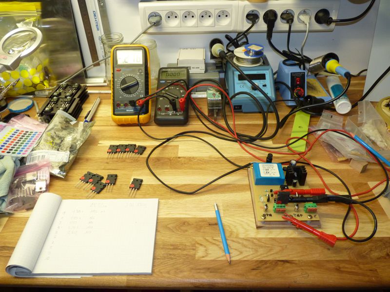
just a few watt in the output is enough to bright the led
then after that you could easily drive any optocoupler to limit anything you want drive, bias ,input ....
working ....
Hello Sakis
ET 2002 "SMPS Pickup Coil" cant find by local supplier
does somebody know substitute or where to buy in europe ?
thread is runing quite for some time now but here is something i found posted in the forum
---a real VI limiter ( sense both V and I )
---active on the output and not the drivers ( ita has been mentioned that when the limiter is active the "load " might destroy the VAS stage )
--- and designed to shunt the P drive , on the lower rail transitor to rail and not the output ( ??? )
Questions are :
A ) is it possible to shunt the drive to the rail instead the output ?
B ) why the designer works directly on the outputs and not the drivers ? ( first time for me to see that ) any opinion if better or worst than the typical limiters we have seen so far ?
Attachments

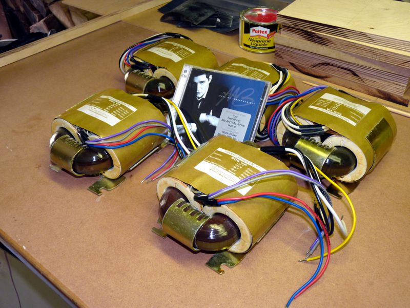
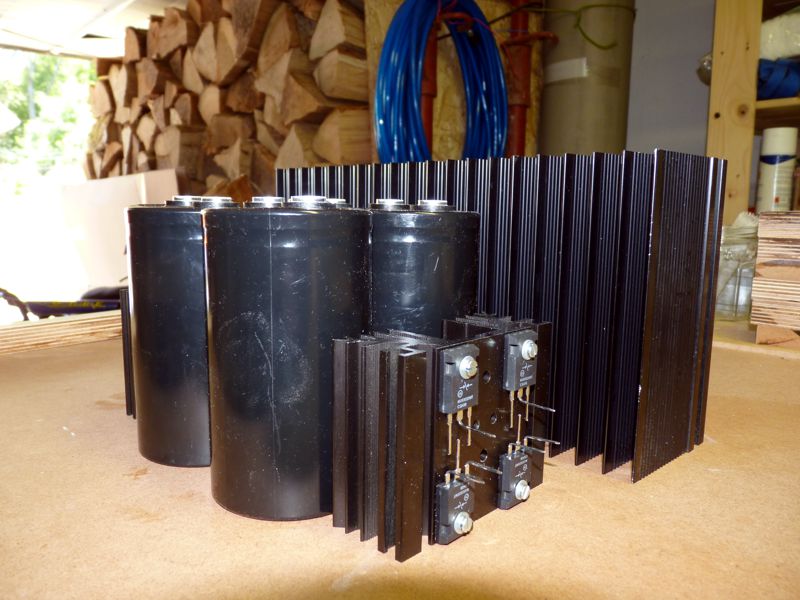
Next step i have, due drastic price reduction, The opportunity to purchase Rcore 500Va 2x36Va trafo. The price was so low that i finaly take five unit and will use 2 for Nbip (1 per chanel)
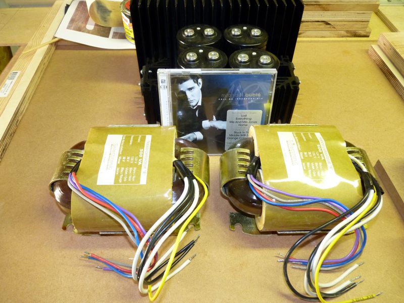
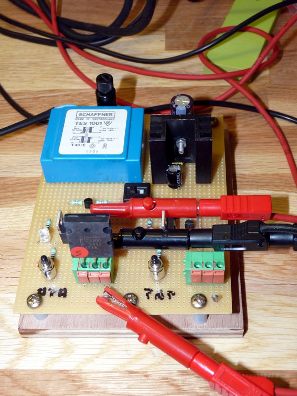
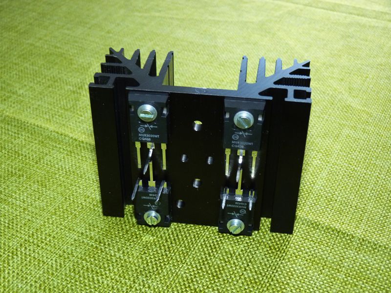
I built rectifier bridge to. The are base on On Semi Mur3020wt diode and rubish TO3 heatsink.
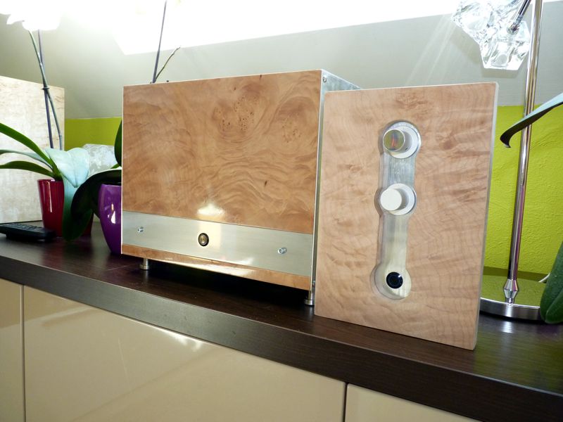
Futher i begin the case buiding : a wood and aluminium mix
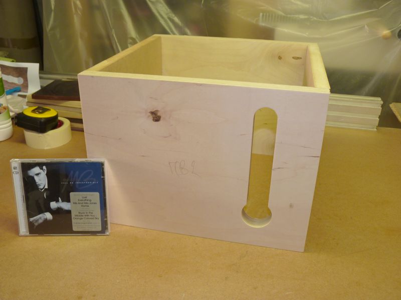
Same spirit as my nmos 200 and as a little 6J6 preamplifier i am on building.
Next step will be 2sc1845 peurchasing and matching, and PCB etching for Nbip, Soft start and Speakers DC protection
Marc
I built rectifier bridge to. The are base on On Semi Mur3020wt diode and rubish TO3 heatsink.
Futher i begin the case buiding : a wood and aluminium mix
Same spirit as my nmos 200 and as a little 6J6 preamplifier i am on building.
Next step will be 2sc1845 peurchasing and matching, and PCB etching for Nbip, Soft start and Speakers DC protection
Marc
You need to invert the driver stage to allow the PNP quasi to work.
Thanks Andrew, so i need to check this more.
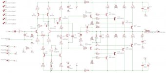
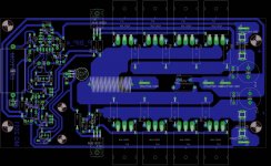
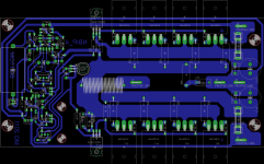
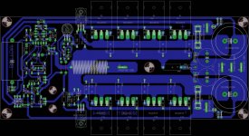
I spend some more time on new NBIP routing job. The goal was to separate the more i can signal input and power input so that any signal wire and power wire are crossing in case arrangement. I keep Quasi first stage layout. This all result in a sigle side PCB without straps.
Note : Emitter resistors have wrong value on Output transistor ; should be 0R5 not 1R
Marc
Attachments
Last edited:
- Status
- This old topic is closed. If you want to reopen this topic, contact a moderator using the "Report Post" button.
- Home
- Amplifiers
- Solid State
- Brother of Quasi